8
Bell crank down
in home position.
C
L
Bell Crank
Adjusting
Screws
Locking
Screws
Top
Bottom
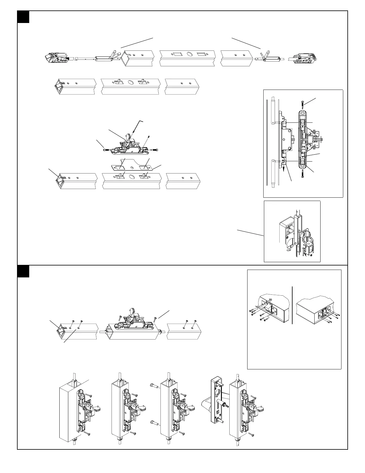
6
Install rods in door and chassis as shown.
C
L
Pivot connecting links
down as shown and slide
latch assemblies into door.
As linkages reach cut outs in door guide them through as shown;
Optional: "WD"
(steel, wood & fire applications).
Attached "L" shaped mounting
brackets to latch and install in
door with proper fasteners as
shown.
Steel - (6) 10-32 x 3/8" F.H.P.M.S.
Wood - (6) #10 x 1" F.H.P.T.S.
Fire Rated Devices Require
(2) "WD" "L" Shaped Brackets.
"Loosen only"; (2) two 3/32" Allen head locking screws using Allen wrench
supplied, remove two adjusting screws shown.
(Do not remove)
3/32" Allen wrench (supplied)
Chassis Assembly
Adjusting Screws
Locking screws
Shim
(Glass doors only.)
Place shim on door as shown (polished side facing outside) aligning holes and
cut outs as required with holes and cut outs in door. Then place chassis on door
allowing connecting links to extend through shim and into bellcrank of chassis as
shown. NOTE: Connecting link brackets should stradle mounting screws,
shaft of thru-bolts, or stand-offs of trim as device is secured to door. See
detail to right.
(4) 10-32 x 1/4" F.H.P.H.M.S.
(Do not use any other screw.)
Metal - (2) 12-24 x 1 1/2" F.H.P.M.S.
Wood - (2) #12 x 1 1/4" F.H.P.T.S.
(For other options; trim, thru bolts, etc.
see below.)
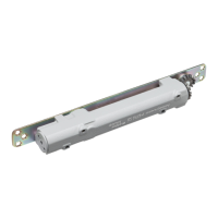
7
Secure chassis and latches to door as shown.
Note: Top
latch fully
extended
and dead
locked.
Optional mounting
Note: Top
latch fully
extended
and dead
locked.
For 3 1/2" stiles or
less on aluminum
doors, place shim
under chassis prior
to mounting on door.
(Finished side to
outside face.)