1
SCREW CHART
(2) #12 x 1 1/4" F.H.P.T.S. (Wood door)
(2) 12-24 x 1 1/2" F.H.P.M.S. (Metal or thru bolts)
(2) #12 x 1 1/4" R.H.P.T.S. (Wood door)
(2) 12-24 x 1" R.H.P.M.S. (Metal or thru Bolts)
(12) 8-32 x 1/4" F.H.P.M.S.
Optional "WD" mounting brackets (4)
(wood, steel and fire)
(4) 10-32 x 1/4" F.H.P.M.S. (Aluminum)
(12) #10 x 1" F.H.P.T.S. (Wood door)
(12) 10-32 x 3/8" F.H.P.M.S. (Metal door)
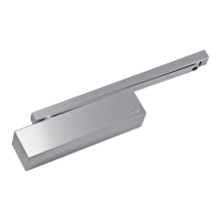
Adjusting screw
(2) 3/32 x 10-32 x 1/2" Allen Head (wrench supplied)
(2) 10-32 x 3/8" F.H.P.M.S.
(6) 8-32 x 1/4" F.H.P.M.S.
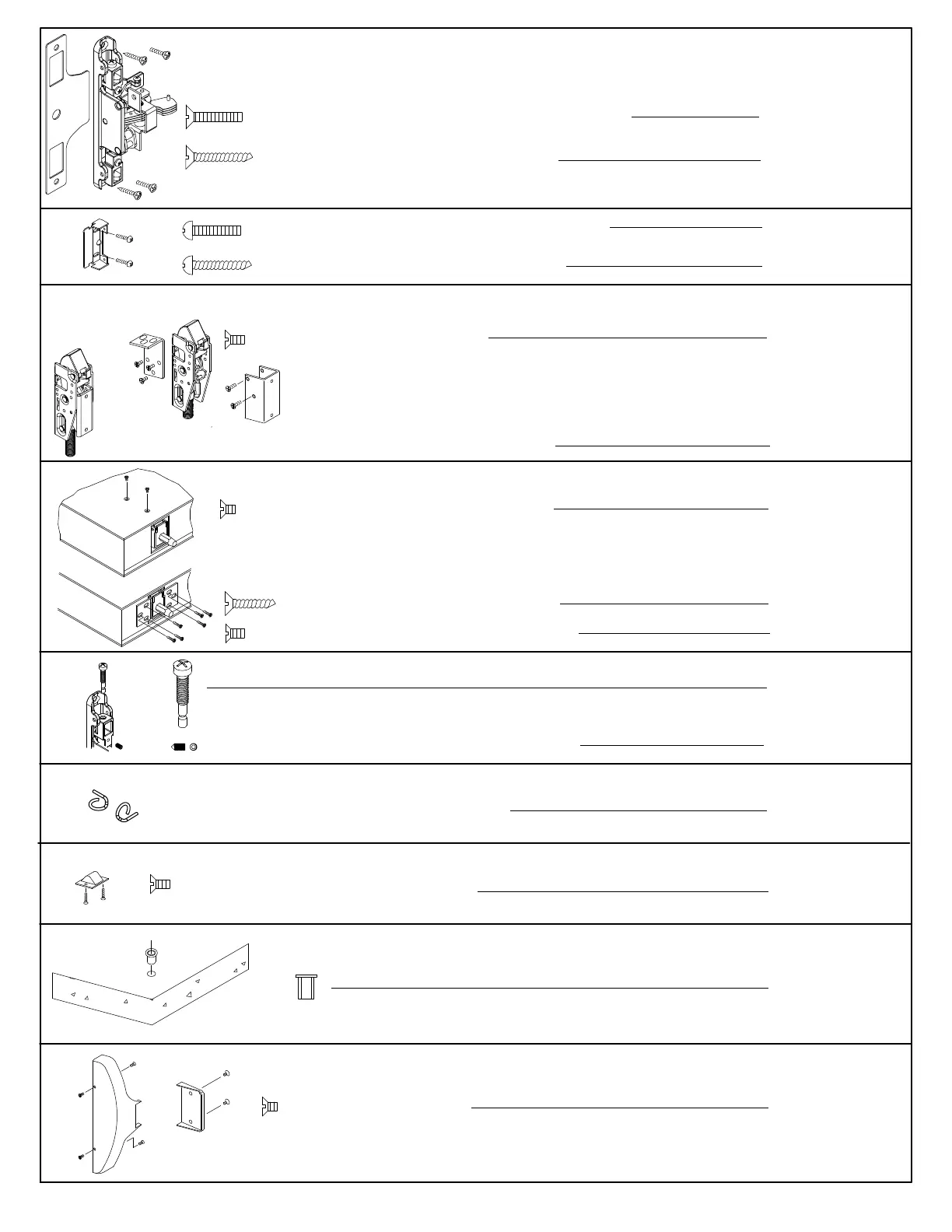
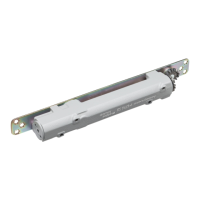
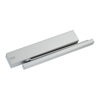
Chassis mounting
End cap bracket
Bracket to latch
Bracket to door
Locking screw
#418 Strike pack
Chassis cover
& end cap
Chassis mounting
End cap bracket
Bracket to door
Bracket to door
#439 Bottom strike
(cement or grout
in place)
(4) 10-32 x 1/4" F.H.P.M.S. (Aluminum)
Bracket to toor
Standard "NS"
latch assembly
(2) Rod retaining clips
Rod installation
Optional: "ALD" Mounting Bracket (2)
(Medium Stile Aluminum Doors)