5
1/8" Pilot for wood
40 5/16"
Pull only
Type of
installation
Single door 1/2"
blade stop
Pairs and
double egress
1 1/4"
2"
"Z" trim
2 1/8"
2 1/16" 2 5/16"
1
2
Based on 1/2"
threshold and 3/16"
clearance between
threshold and door
after door is hung.
Minimum Stile
1 1/32"
2"
Minimum
Fire rated
& wood door
1 1/4"
2"
2 7/8"
2 5/8"
Typical pair of doors
Finished floor
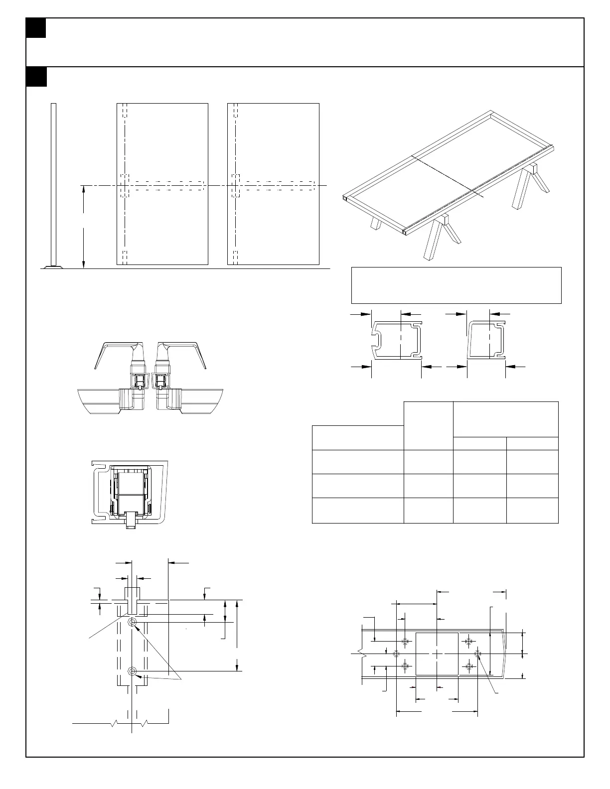
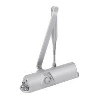
With door lying on saw horses, open box, layout all parts and verify prior to starting installation. See page (1) one
for parts.
Note: If this is a retro-fit from current 5100 see page 18 prior to proceeding.
Door preperation
Chassis
horizontal
ref. line
Chassis
vertical
ref. line
Min. Stile
Min. Stile
Beveled edge door
Rounded edge door
Minimum
vertical
ref. of
chassis
Vert. ref.
Vert. ref.
Latch case prep (Top & Bottom)
1/8"
Top of Door
3/8"
3/4"
1 1/2"
3 5/16"
7/32" Dia. hole
82 degree countersink
to 3/8" dia. (2) places
7/16"
10-32 Tap
(6) Places
2 7/8"
1 1/2"
3/4"
7/8"
C
L
Latch
3/4"
1 1/2"
1 1/8"
C
L
Latch & chassis
1 7/16"
7/8"
Backset or vertical reference is measured from
outer edge of door as shown. Minimum stile is
less glass stop.
"Cutout" Top
C
L
Latch
Panic device (metal and wood door)
Fire device (metal and wood door)
of door only.
Panic device (aluminum door)
Chassis template
located at rear of
booklet. Cut and
tape in place.
Lay out horizontal
and vertical refer-
ence lines.
Note: Metal edge may be required on
fire door applications.
Note: On narrow stile,
vertical center line of
chassis may not be
on same center line
as latch.
Narrow stile