DORMA
1
2
3
6
4
5
7 8
9
2
1
1 2
ON
1 2
ON
3DORMA
ES 200 / ES200-2D
—
1
2
3
6
4
5
7 8
9
2
1
1 2
ON
1 2
ON
3DORMA
ES 200 / ES200-2D
—
ES 200
42
FST Original settings Digitale inputs Digitale outputs
1 2 3 4 1 2 3 4
DCW Adresse 48
1 2
ON
1 2
ON
3DORMA
ES 200 / ES200-2D
—
Secondary closing edges Sensor 1
X
Secondary closing edges Sensor 2
X
Main closing edge
●
X
Panic closing function
X
Door status contact 1
●
“DOOR OPEN”
X
Door status contact 2
●
“DOOR CLOSED”
X
Door status contact 3
●
“OPERATIONAL FAULT”
X
Door status contact 4
●
Bell contact
X
DCW Adresse 49
1 2
ON
Airlock function impulse Entrance (disables the door)
X
Pharmacy control impulse
●
X
Disable airlock Entrance (disables the door)
X
Panic closing function
X
Door status contact 5
●
Door closed
X
Door status contact 6 Disable airlock (exit)
X
Door status contact 7 Airlock impulse (exit)
X
Door status contact 8
●
Bell contact
X
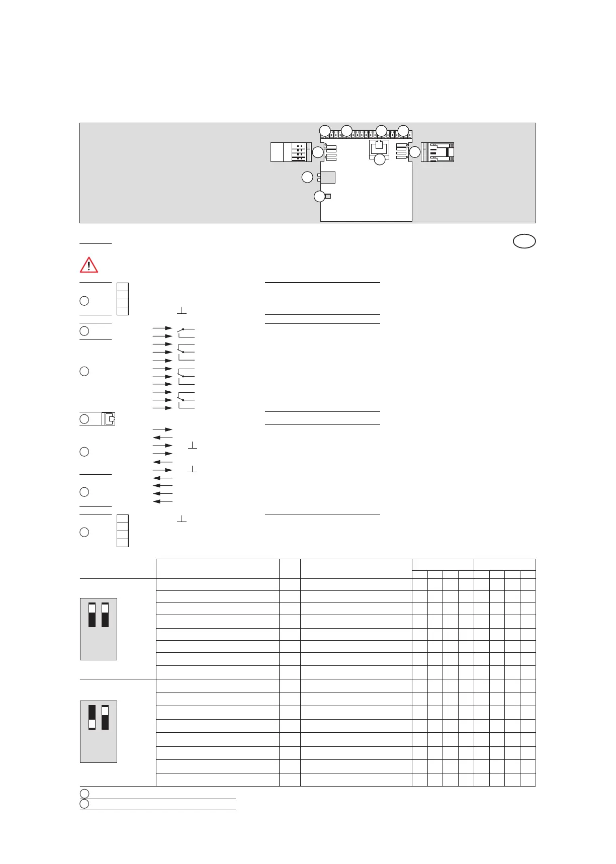
OUT 1 Digitale outputs
DCW Interface
DCW Interface
DIP switch
LED status indicator
OUT 2
OUT 3
OUT 4
COM 1 Programming interface
IN 1 Digitale inputs
IN 2
IN 3
IN 4
1
2
3
4
5
6
7
8
9
10
11
22 GND
23 Signal B
24 Signal A
25 + 27 V DC
29 + 27 V DC
28 Signal A
27 Signal B
26 GND
12 + 27 V DC
13 IN
14 GND
15 + 27 V DC
16 IN
17 GND
18 IN +
19 IN –
20 IN +
21 IN –
C
NO
NC
C
NO
NC
C
NO
NC
C
NO
When connecting a DCW device via cable, the wiring has to be checked again. Interchanged DCW connections
(e.g. 27 V DC to A or B), or missing GND connection, may destroy all connected DCW devices.
Breaking capacity of digital outlets:
1 A 30V DC
0,5 A 125V AC
0,3 A 60V DC
Description and terminal connections
EN
3
4
5
6
7
8
9
2
1