8
9
12
13
19
21
22
23
10
11 14
15 16
17
18
20
1
2
3
4
5
6
7
ES 200
—
8
9
12
13
19
21
22
23
10
11 14
15 16
17
18
20
1
2
3
4
5
6
7
ES 200
—
8
9
12
13
19
21
22
23
10
11 14
15 16
17
18
20
1
2
3
4
5
6
7
ES 200
—
8
9
12
13
19
21
22
23
10
11 14
15 16
17
18
20
1
2
3
4
5
6
7
ES 200
—
8
9
12
13
19
21
22
23
10
11 14
15 16
17
18
20
1
2
3
4
5
6
7
ES 200
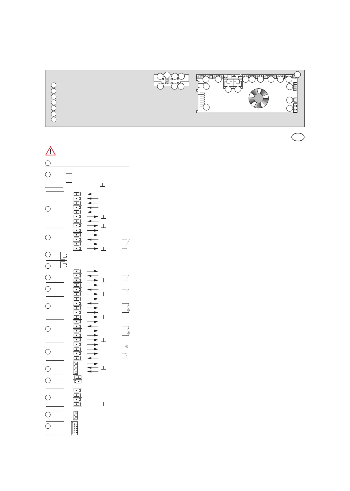
40
FST-Interface
1 Program switch Off
2 AUTOMATIC
3 EXIT ONLY
4 PARTIAL OPEN
5 PERMANENT OPENING
6 GND GND
7 NIGHT / BANK
8 GND GND
9 + 27 V DC Locking device Power supply
10 Lock
11 Status report
12 Unlock
13 GND GND
14 + 27 V DC External activation Power supply
15 External detector
16 GND GND
17 + 27 V DC Internal activation Power supply
18 Internal detector
19 GND GND
20 + 27 V DC Presence 2 Power supply
21 Receiver 2
22 + 27 V DC Power supply
23 Transmitter 2
24 GND GND
25 + 27 V DC Presence 1 Power supply
26 Receiver 1
27 + 27 V DC Power supply
28 Transmitter 1
29 GND GND
30 Service Service outlet (open Source, 1,5A)
31 + 27 V DC Power supply
32 GND
33 EMERGENCY OFF EMERGENCY OFF
34 Inhibit
35 GND Power supply GND
36 + 35 V DC Power supply
37 Battery Battery +
38 Battery –
39 + 27 V DC DCW Interface
40 Signal A
41 Signal B
42 GND
43 Motor
44
Inkremental encoder
48 + 27 V DC DCW Interface
47 Signal A
46 Signal B
45 GND
When connecting a DCW device via cable, the wiring has to be checked again. Interchanged DCW connections
(e.g. 27 V DC to A or B), or missing GND connection, may destroy all connected DCW devices.
Control System basic module
1
LED 1
2
LED 2
3
7-Segment-display menu navigation
4
+ "Plus" pushbutton
5
– "Minus" pushbutton
6
SEL "Select" pushbutton
7
SERV “Service” pushbutton
Description and terminal connections
EN
8
9
10
11
12
13
14
15
16
17
18
19
20
21
22
23
Interconnection LON-Adapter
Service Interface to PDA