+
BN
WH
+27 V DC
GND
1
2
3
4
5
6
7
8
9
10
11
12
13
14
15
16
17
18
19
20
21
22
23
24
25
26
27
28
29
30
31
32
33
34
35
36
37
38
ES 200
—
+
BN
WH
+27 V DC
GND
1
2
3
4
5
6
7
8
9
10
11
12
13
14
15
16
17
18
19
20
21
22
23
24
25
26
27
28
29
30
31
32
33
34
35
36
37
38
ES 200
49
Anschlußplan Melder
Wiring diagram radar
Beschreibung und
Klemmendefinition
DE
Steuerung
Description and
terminal connections
EN
Control system
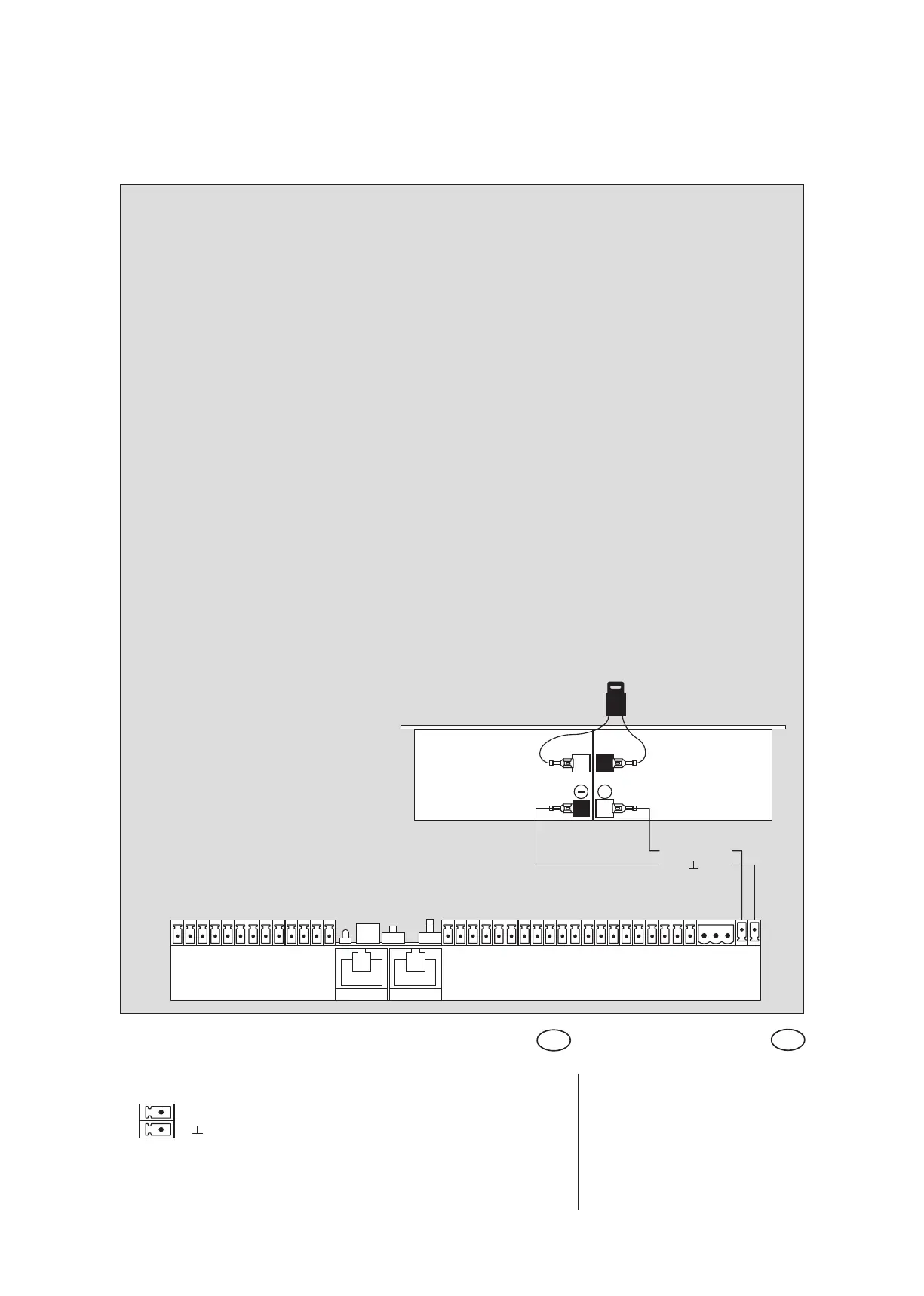
37 +27 V DC
38 GND
Akku-Anschluß Battery
Steuerung ES 200 Grundmodul
Control system ES 200 Basic module
Sicherung
Fuse
Akku
Battery
10A
Akku:
• NUR zur Funktionsprüfung und direkt vor
Inbetriebnahme anschließen.
• Vor Reparaturen: Verbindung trennen.
Battery:
• Attach ONLY for the functional test and
immediately before the commissioning.
• Disconnect the battery before servicing the ES-200