25 24 23 22
OFF
ON
2 1 29 28 27 26
19
18
16
14
13
12
11
10
9
8
7
6
5
4
3
2
1
21
20
17
15
25 24 23 22
OFF
ON
2 1 29 28 27 26
19
18
16
14
13
12
11
10
9
8
7
6
5
4
3
2
1
21
20
17
15
1 2
ON
1 2
ON
25 24 23 22
OFF
ON
2 1 29 28 27 26
19
18
16
14
13
12
11
10
9
8
7
6
5
4
3
2
1
21
20
17
15
25 24 23 22
OFF
ON
2 1 29 28 27 26
19
18
16
14
13
12
11
10
9
8
7
6
5
4
3
2
1
21
20
17
15
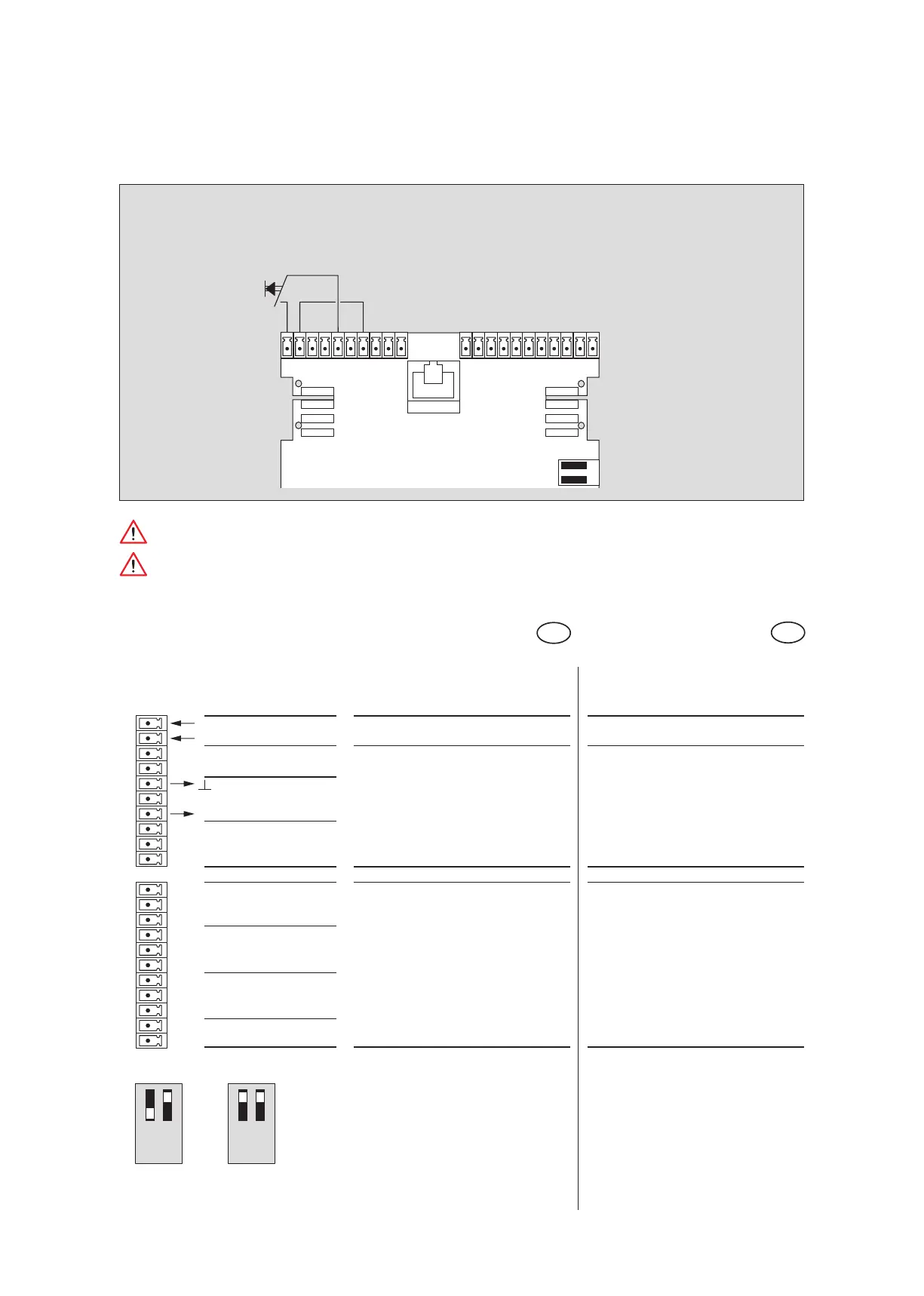
ES 200
6060
Anschlußplan Panikschließung
Wiring diagram panic closing
Paniktaster
Emergency switch
Funktion wird über PDA eingestellt
function setting via PDA
IN 3
IN 4 Panikschließung Panic closing
OUT 1
IN 2
OUT 4
IN 1
OUT 2
OUT 3
Digitale Ausgänge Digital output
Beschreibung und
Klemmendefinition
DE
Steuerung
Digitale Eingänge
Description and
terminal connections
EN
Control system
Digital input
DCW Adresse 49 oder Adresse 48 DCW Adress 49 or Adress 48
21 IN -
20 IN +
19
18
17 GND
16
15 +27 V DC
14
13
12
11
10
9
8
7
6
5
4
3
2
1
ES 200 Funktionsmodul
ES 200 Function module
Die Funktion Panikschließung unterliegt besonderen gesetzlichen und rechtlichen
Bestimmungen. Daher immer die länderspezifischen Richtlinien beachten!
The panic closing function is subject to special legal provision,
therefore the provisions of the relevant country must be observed!