ES 200
83
DEEN
ES 200 / ES 200-2D Service-Key
The service key is the linking element between the PDA (Personal Digital Assistant) and the ES 200 basic module.
It may also be used with the basic module without PDA in order to disable the control keys of the control unit or to update the
software of the basic module.
Operation via PDA
The PDA is connected to the service key (9-pole SUB D plug) with a serial connecting cable. Connect the service key via the
connection cable to the basic module (Port 13 behind the service keys). Establish a connection between the control unit and
the PDA (see ASP operating instructions). The LED status indicator on the service key turns green. Now the settings like driving
parameters, system data etc. may be changed via the PDA. An upload must be performed in case that any settings have been
changed. The LED status indicator of the service key lits red, in the event that an error has occured during upload. In this case
the upload must be repeated. Following a successful upload the LED is green. The PDA may also be used to install a new soft-
ware version on the service key. Software upload from PDA to service key: See "ES 200" ASP data base recording.
Software update of ES 200 basic module via service key
The service key must contain the latest software version.
The software update may not be done while the door is under operation, as it could get out of control.
Take the ES 200 sliding door out of operation (set program switch to OFF, or use the EMERGENCY OFF pushbutton if necessa-
ry.) Press and hold the start push button for three seconds. The LED status indicator on the service key flashes orange while it
performs the update. It flashes red in the event that an error occurs during upload. In this case, the upload must be repeated.
Following a successful upload the LED turns green.
Following a software update, the power supply must be reset (rechargeable battery pack and power plug must be removed
for a short time) and a learning cycle has to be performed. The door settings must be checked and reset if required (e.g.
locking type, motor type, operation via rechargeable battery pack etc.).
Enabling the control panel via service key.
When the basic module of the ES 200 control system is disabled, the control panel can be enabled by connecting the service key
to the basic module via the RJ45 plug of the connection cable. The settings can now be changed. As soon as the service key is
disconnected from the control unit, the control panel is disabled automatically.
LED status indicator
LED status indicator Update PDA service key Update service key basic module
Green Update successful Update successful
Orange Update in progress
Red Error during update
Orange (flashing) Update in progress
Red (flashing) Error during update
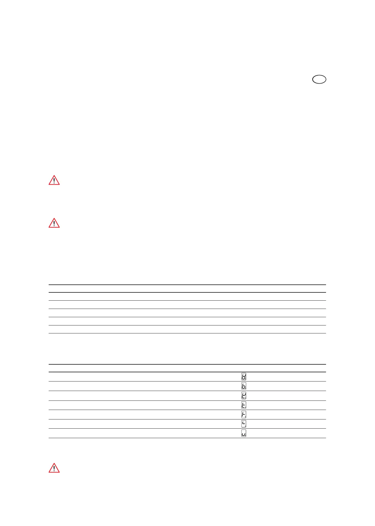
Troubleshooting
The basic module indicates an error code in the event of an incomplete update. The LED status indicator on the service key goes
out.
Error code Possible reasons Error display
01 System
03 Program sequence
05 RAM error
07 Interrupt Vector not defined
15 RAM-check
31 DMOS-Clock Handler sequence (DCW-Timing)
Bootloader CRASH ROM checksum error
Should one of the above-mentioned errors occur, the system must be disconnected from power supply and the ES 200 control
unit has to be programmed again.
The system cannot be updated via infrared device.