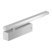
dormakaba TS93 GSR/EMF T 1A, 1I, 2 Installation Instructions
08280031 08-2019TS93 GSR Surface Applied Closers
8
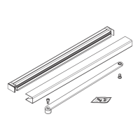
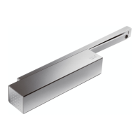
Wiring conduit
Coordinator system
. Installing conduit for EMF
Fig.
From VDC
power supply
Cable clamps
.. Secure conduit to mounting surface with cable
clamps included.
• Use two - x /" screws.
.. Feed wires through conduit.
NOTE: Must run inactive solenoid wire through conduit
on wall side of track.
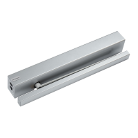
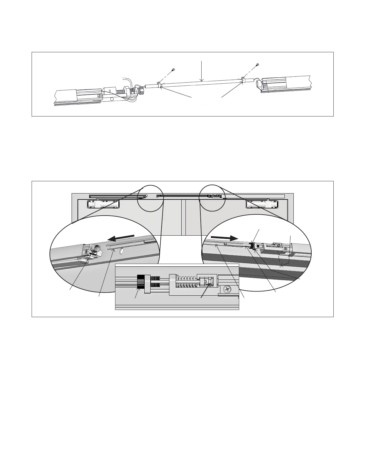
. Installing coordinator system (continued)
Fig.
Left hand door
(Active)
Right hand door
(Inactive)
Clamping
rod
Trigger
dial
Connecting
channel
Set
screw
Locking
pin
Plastic
guide
Connecting
channel
Clamping plate
Trigger dial
.. Open active leaf to retract clamping rod.
.. Active door: Insert connecting channel into
trigger dial.
.. Inactive door: Insert connecting channel into
plastic guide.
.. Unwind trigger dial (away from door frame)
until active door starts to close. Clamping plate
should be perpendicular to clamping rod.
.. Tighten set screw to secure trigger dial.
NOTE: The locking pin can be discarded once system
has been installed.
Conduit
 Loading...