10 DR
®
SNOW BLOWER
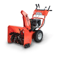
3. Remove the Cotter Pin from the Auger Control Lever and remove the Cable
end from the Lever (Figure 8).
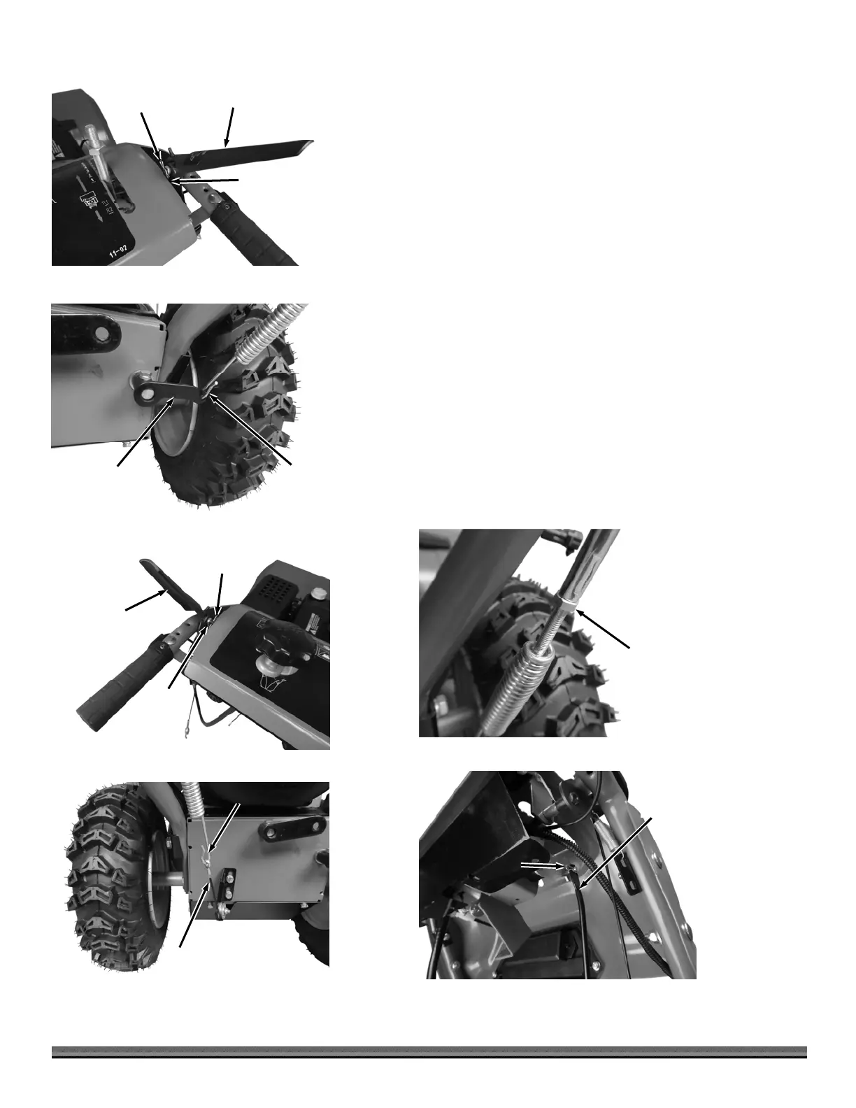
4. Attach the Spring Hook of the Auger Control Cable into the Tension
Connector at the right side of the machine (Figure 9).
5. Reinstall the Cable end to the Lever and secure with the Cotter Pin (Figure
8).
6. Remove the Cotter Pin from the Drive Control Lever and remove the Cable
from the Lever Pin (Figure 10).
7. Attach the Spring Hook of the Drive Control Cable into the Pulley Wire at
the left side of the machine (Figure 11).
Note: Ensure that the Cable is routed on the correct side of the Grip Heater Wire as
you perform the next step.
8. Reinstall the Cable end to the Lever Pin and secure with the Cotter Pin
(Figure 10).
9. Check the Jam Nuts on the Auger Control Cable and Drive Control Cable to
ensure they are tight (Figure 12). Tighten as needed using a 6mm Wrench
to hold the Cable and an 8mm Wrench to tighten the Nut.
10. Remove the Pin and install the upper end of the Shift Connector Bar (Figure
13).
Pin
Figure 13
Shifter
Connector
Bar
am Nut
Figure 12
Drive Control
Lever
Figure 10
Cotter
Pin
Cable
Spring Hook
Figure 11
Pulley
Wire
Spring
Hoo
Figure 9
Tension
Connecto
uger Control
Leve
Figure 8
Cotter
Pin
Cable