CONTACT US AT www.DRpower.com 9
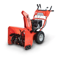
Smaller Parts Bags (Figure 5):
Item# Part # Description Qty
1 ......... 40290 .............. Bolt, M6x16 ............................................................. 2
2 ......... 40347 .............. Washer, Spring, 6mm ............................................. 2
3 ......... 40345 .............. Washer, Flat, 6mm ................................................. 2
4 ......... 40424 .............. Key, Off Switch ........................................................ 2
5 ......... 42532 .............. Tool, Spark Plug ...................................................... 1
6* ....... 40296 .............. Bolt, Shear, Impeller, M6x35 (Pro-24).................... 2
40297 .............. Bolt, Shear, Impeller, M6x40 (All except Pro-24) ... 2
7* ....... 40313 .............. Nut, Jam M6 ........................................................... 2
8* ....... 40321 .............. Bolt, Shear, Auger (All except Pro-24) .................... 2
9* ....... 40278 .............. Nut, Jam, M8 (All except Pro-24) ........................... 2
10* ..... 40311 .............. Bolt, Shear, Auger (Pro-24) .................................... 2
11* ..... 40317 .............. Pin, Cotter, Auger Drive (Pro-24) ........................... 2
12 ....... 40098 .............. Block, Chute ............................................................ 3
13 ....... 40325 .............. Screw, M6 X 16 ....................................................... 6
14 ....... 40347 .............. Washer, Spring, 6mm ............................................. 6
*Spare Shear Hardware (not needed for assembly)
Compare the contents with the “Smaller Parts Bags” list above. If you have any
questions please contact us at www.DRpower.com or call 1-800-DR-OWNER
(376-9637) for assistance.
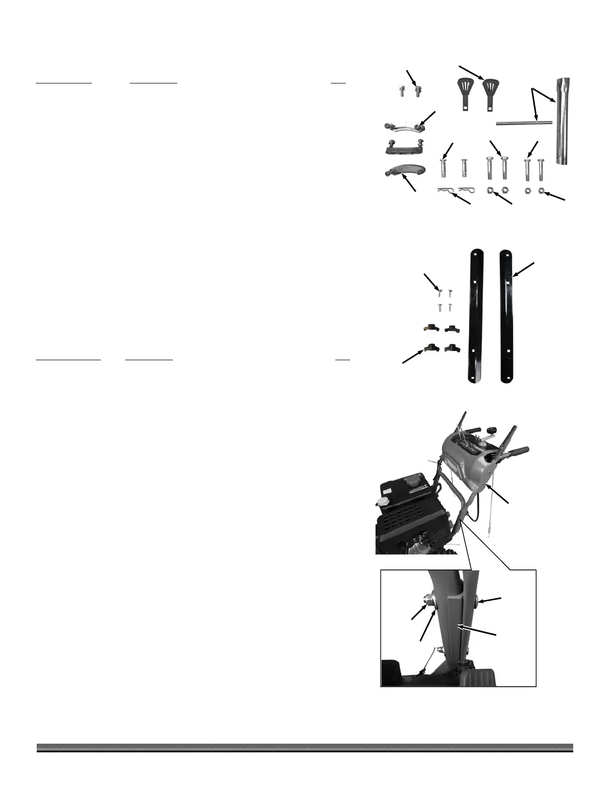
Drift Cutter Parts (Figure 6):
Item# Part # Description Qty
1 ............. 40350 .........Drift Cutter .................................................................. 2
2 ............. 40303 .........Bolt, M8x20 ................................................................. 4
3 ............. 40351 .........Nut, Wing, M8, Plastic ............................................... 4
Compare the contents with the “Drift Cutter parts” list above. If you have any
questions, please contact us at www.DRpower.com or call 1-800-DR-OWNER
(376-9637) for assistance.
Assembly Instructions
Tools Needed:
13mm Wrench
6mm Wrench
8mm Wrench
11mm Wrench
14mm Wrench
17mm Wrench
Wire Cutters
Eye Protection
1. Have a helper hold the upper Handlebar Assembly in position on the lower
Handlebar (Figure 7).
2. Place the Adapter Plates between the upper and lower Handlebar
Assemblies and secure with The M8 X 55 Bolts, 8 X 22 X 2 Washers and M8
Jam Nuts using a 13mm Wrench.
Note: Ensure that the Bolt Heads are on the outside of the Handlebar and the
square portion of the Bolts go fully into the squares in the handlebar.
Figure 5
1, 2, 3
4
5
12
6
13, 14
7
8
9
11
10
Handlebar
ssembly
Figure 7
rmrest
Pa
Carriage
Bolt
am Nut
Washer
Figure 6
1
2
3