CONTACT US AT www.DRpower.com 11
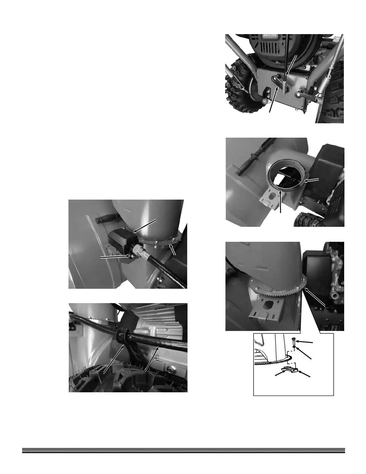
11. Remove the Locknut from the lower Gimbal end of the Shift Connector Bar
and insert the threads through the Shift Connector at the center of the
machine (Figure 14).
12. Secure the Gimbal with the Locknut using a 11mm Wrench on the Gimbal
and a 13mm Wrench on the Locknut.
13. Ensure the Gimbal’s upper Jam Nut is tight using a 14mm Wrench.
14. Install the Chute Washer onto the Auger Housing Flange (Figure 15).
15. Place the Chute Assembly onto the Housing Flange and secure with the
three Fixed Blocks, six M6 X 16 Screws and six 6mm Spring Washers using
a Philips Head Screwdriver (Figure 16).
Note: Ensure that the Fixed Block Tabs are facing down and go underneath the
Housing Flange.
16. Position the Discharge Chute Rotation Bracket and hold it against the
Chute Gear as you secure it with the two Screws, Lock Washers, and Flat
Washers using a 10mm Wrench (Figure 17).
17. Place the Rotation Bracket Cable into the Connecting Plate (Figure 18).
Connecting
Plate
Figure 18
Chute
Rotation
Cable
Rotation
Bracket
Figure 17
Bolt with
Spring
Washer and
Flat Washer
Chute
Teeth
Figure 16
Fixed Block Tab
Goes under
Housing Flange
Fixed
Block
Spring
Washer
Screw
Chute
ssembly
Fixed Block
Housing
ssembly
Chute
Washe
Figure 15
uger
Housing
Flange
Shift Connector
Figure 14
Shift
Connector
Bar