26 DR
®
SNOW BLOWER
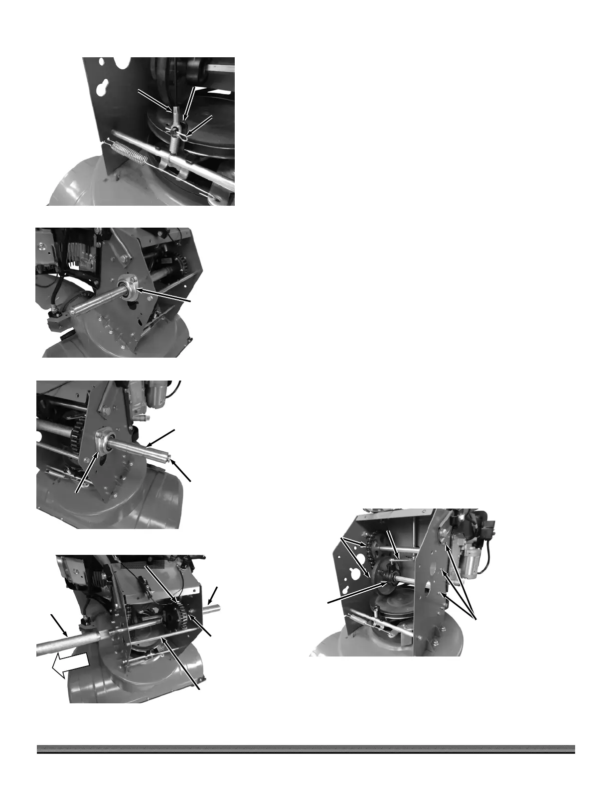
7. Remove the Pin and remove the Traction Cable from the Traction Drive
Bracket (Figure 72).
8. Remove the two Bolts, Lock Washers, Flat Washers, and Locknuts that
secure the left side Wheel Bearing Assembly using two 13mm Wrenches
and remove the Bearing Assembly from the Axle (Figure 73).
9. Hold the larger diameter outer Shaft of the right-side Axle Shaft while
hitting the smaller diameter inner Shaft with a Dead Blow Hammer (Figure
74). This will push the smaller Shaft in, separating it from the larger outer
Shaft.
Note: A Brass Punch may be needed to push the smaller diameter Shaft in further
to separate the two Shaft sections.
10. Remove the two Bolts, Lock Washers, Flat Washers, and Locknuts that
secure the right side Wheel Bearing Assembly using two 13mm Wrenches.
Remove the Bearing Assembly from the Axle.
11. Remove the two rear Strut Bolts and Lock Washers using a 10mm Wrench
and remove the Strut (Figure 75).
Note: Pay attention to the orientation of the Differential on the Shaft before you
remove it (Bolt heads facing left side of machine) to ensure it is replaced in the same
orientation during assembly.
12. Remove the Long Shaft, Short semi-Shaft, Shaft Sleeve and Differential from
the machine.
Note: You may need to tap the Differential with a Dead Blow Hammer to separate
it from the Shaft splines for removal.
13. Remove the six Bolts, Lock Washers and Flat Washers (three each side)
that secure the Friction Wheel Assembly using a 10mm Wrench (Figure 76).
14. Carefully remove the Friction Wheel Assembly from the machine ensuring
that everything stays together.
Note: Ensure that the Chain side of the Friction Wheel Assembly stays together
during the following steps. This will ensure easier installation.
Friction
Wheel
ssembly
Figure 76
Shift Fork
Shift
Bearing
Hardware
Differential
Figure 75
Long
Drive
Shaft
Short
Drive
Shaft
Rear Strut
Shaft
Sleeve
Short (Outer)
Drive Shaft
Figure 74
Long (Inner)
Drive Shaft
Bearing
Wheel
Bearing
ssembly
Figure 73
Traction
Cable
Figure 72
Pin
Traction
Drive Bracket