22 Dräger Interlock 5000/7000
Description
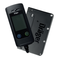
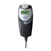
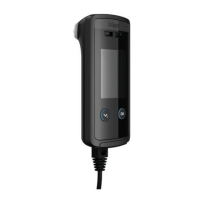
Legend
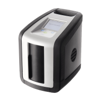
1 Holster for handset
2 Protective case for handset (optional)
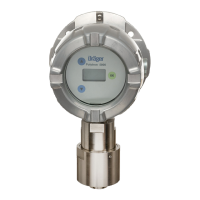
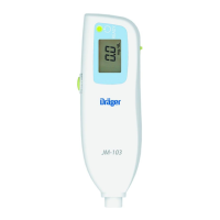
3 LED
4 Air outlet
5 Down/Menu button
6 OK button
7 Mouthpiece
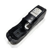
8 Expansion box connection
9 GPRS module connection
10 Control unit
11 Socket for plug connector on connection cable
12 Camera connection
13 IR interface
14 Handset connection cable
15 Socket for plug connector on connection cable
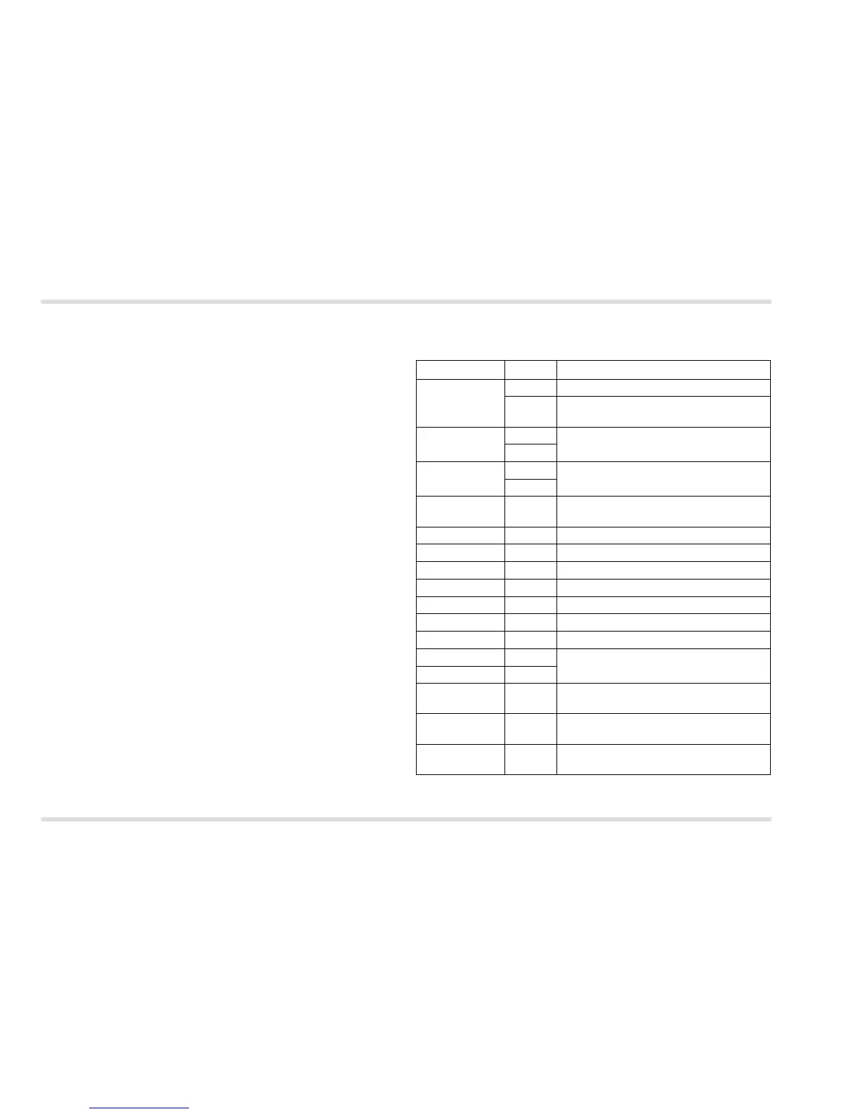
2.2 Description of the connection leads on
the control unit
Label Colour Description
1 grey Connection to starter relay
brown "Starter relay" connection on the ignition
switch
2 orange Relay for connection, such as for
headlights (optional)
1)
1) Only Interlock 7000
purple
3 white Relay for connection, such as for horn
(optional)
1)
yellow
4 blue "Ignition" connection of the ignition
switch
5 black Earth
6 red Positive power supply
7 white Output switched to PIN 10
8 white Output switched to PIN 10
9 white Output switched to PIN 11 (GND)
10 white Power supply (for PINs 7 and 8)
11 white Earth connection (inputs/outputs)
12 LED+ white External LED display connection
(optional)
1)
13 LED– white
14 white Input, switching to earth
(optional)
15 white Input, switching to positive
(optional)
16 white Input, switching to positive
(optional for D+)