24 Dräger Interlock 5000/7000
Installation
Draw connecting leads up along steering column cable harness and
temporarily secure in place. If leads are too short for connection to the
ignition switch cable harness, re-position the control unit.
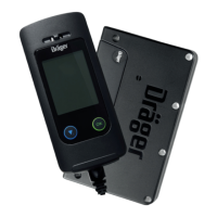
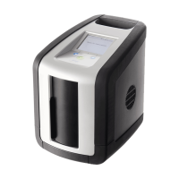
3.3.2 Handset
Decide upon mounting location for the holster for the handset
ensuring minimal obstruction by the handset and easy accessibility
for the driver.
If the cable from the control unit to the handset is too tightly
stretched or too short, re-position the handset, the control unit
or both.
3.4 Connecting the leads
3.4.1 Tracing the vehicle ignition wires
Detach the steering column cover and padded screens to access
the ignition switch and cable harness.
If the vehicle wiring is unknown, the relevant documents on the
vehicle must be consulted or the circuits will have to be traced
using a multimeter or a 12 V or 24 V test light:
1. Switch multimeter to an appropriate DC measuring range.
2. Connect one lead to vehicle earth, for example onto the vehicle
chassis.
3. Test and identify the connections at the back of the ignition switch
with the second test lead:
switch the ignition switch slowly on to trace the voltage at different
key positions.
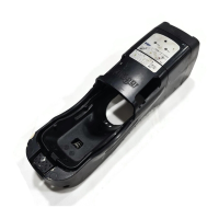
NOTICE
When installing the control unit, ensure that the
connection cable for the handset is secured against
tensile load (e. g. using a cable tie).
WARNING
Do not install holster for the handset in front of
airbags.
i
i
!
A
I
R
B
A
G
NOTICE
Check for any installation instructions specific to the vehicle,
and if these exist, continue by following those instructions.
A list of available installation instructions can be obtained
from Dräger.
"START"
key position
"IGNITION"
key position
Other
key positions
Lead
starter relay
Voltage – – – – – –
Lead
ignition
Voltage Voltage – – –
Positive
supply lead
Voltage Voltage Voltage
i
i