3
● Dichtflächen am Gastransmitter
gegebenenfalls reinigen. In jedem Falle
die Dichtflächen und den Boden der
Messküvette vollständig trocknen lassen.
● Flachdichtung (1) und Ring (2) mit
eingeschraubten Tüllen auf den
Gastransmitter aufsetzen und mit vier
Schrauben M5 x 12 und
Unterlegscheiben gleichmäßig fest
anziehen.
● Werden die Tüllen (Gaseinlass und
Gasauslass) nicht benötigt, sind diese
gasdicht zu verschließen, z. B. durch
Verbindung mit einem kurzen Schlauch,
gegebenenfalls leicht anfeuchten.
Montage Flowcell bzw. Ferntestadapter:
3 Flowcell PIR 7000 Duct (Bestell-Nr.
68 11 945, siehe Seite 4) bzw.
Ferntestadapter PIR 7000 Duct (Bestell-
Nr. 68 11 990, siehe Seite 4).
4 Die zwei Elastomer-Winkeltüllen innen
anfeuchten und auf die Flowcell bzw. den
Ferntestadapter bis zum Anschlag
aufschieben.
5 Die Flowcell bzw. den Ferntestadapter in
den Ring einpassen. Die Winkeltüllen auf
die Tüllen im Ring aufschieben.
● Anschließend die Flowcell bzw. den
Ferntestadapter mit den zwei Schrauben
festziehen.
6 Falls erforderlich: Den Spritzschutz mit
den zwei Schrauben auf dem
Gastransmitter montieren.
7 Montagewinkel auf den Gastransmitter
aufsetzen und mit sechs Schrauben
M5 x 10 und Unterlegscheiben
befestigen.
8 Bei der Positionierung des
Montagewinkels und, sofern vorhanden,
des Spritzschutzes die
Strömungsrichtung beachten.
Der Gaseinlass muss im Rohr in die
Strömungsrichtung zeigen.
9 Gastransmitter auf das Rohr aufsetzen
und den Montagewinkel mit den drei
Schrauben M6 x 16, Unterlegscheiben
und Muttern locker an der Rohrhalterung
befestigen.
● Zur Erleichterung der Montage, Dichtung
im Rohr mit Wasser leicht anfeuchten.
● Gastransmitter in die Dichtung drücken,
bis zum Anschlag.
● Die drei Schrauben festziehen.
● Danach den Gastransmitter auf der
gegenüberliegenden Seite mit zwei
Schrauben M6 x 16 auf der
Rohrhalterung befestigen.
● System auf ausreichende Gasdichtigkeit
überprüfen.
Gastransmitter in die Wartungsposition
bringen:
9 Alle fünf Schrauben M6 x 16 an dem
Montagewinkel lösen.
● Gastransmitter aus der Dichtung
herausziehen und um 90
o
drehen.
● Zwei Schrauben wieder festziehen.
HINWEIS
Für eine einwandfreie Messung ist die
Strömungsrichtung im Rohr und die richtige
Ausrichtung des Spritzschutzes von
entscheidender Bedeutung.
00533011_02.eps
2
1
00633011_02.eps
6
3
4
5
00733011_02.eps
8
7
00833011_02.eps
9
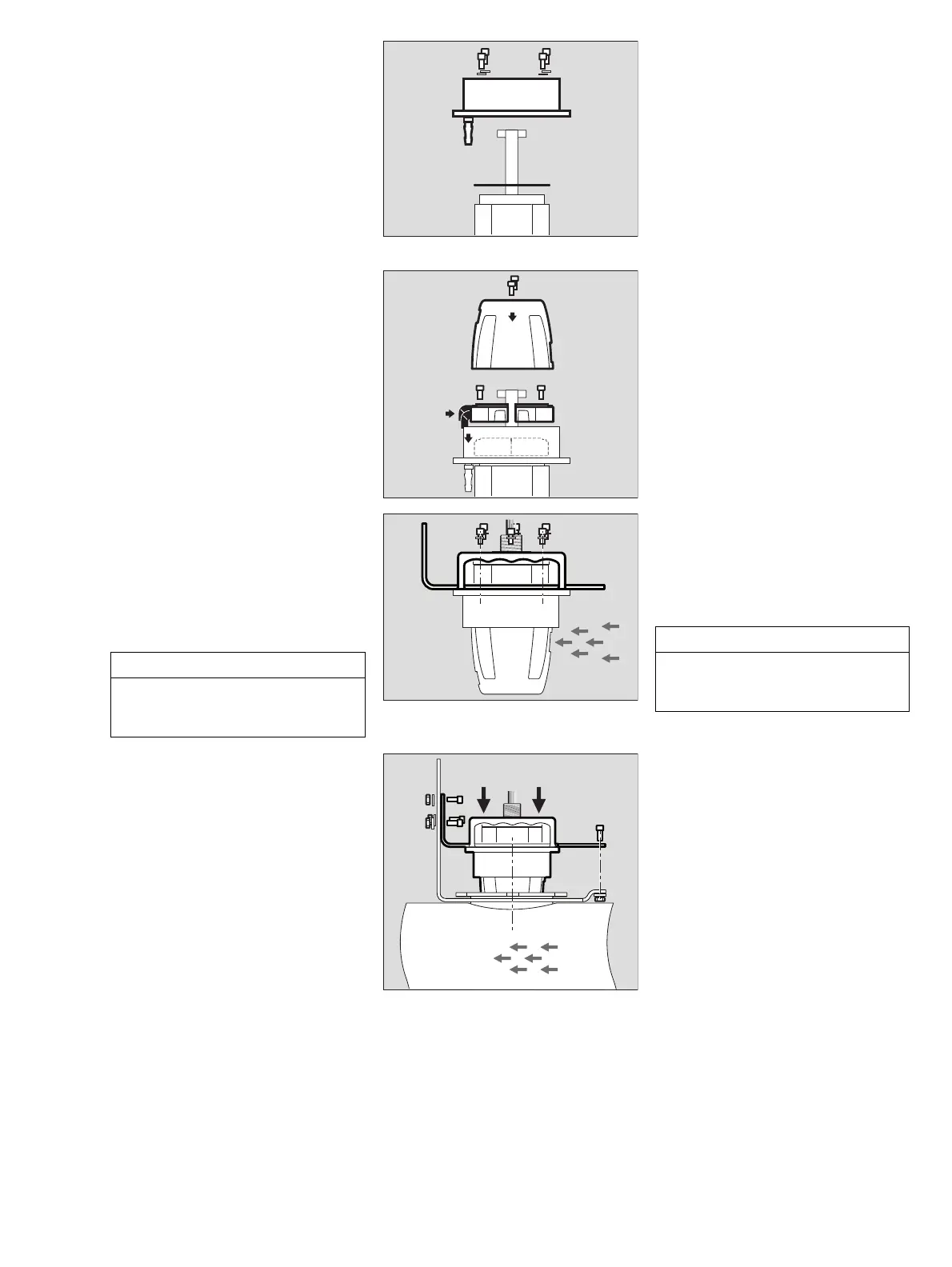
● Clean sealing surfaces on the gas
transmitter, if required. Always allow the
sealing surfaces and the base of the
measuring cuvette to dry completely.
● Position the flat gasket (1) and the ring
with screwed-in nozzles (2) onto the gas
transmitter and secure it by evenly
tighten four screws M5 x 12 with
washers.
● If the nozzles (gas inlet and gas outlet)
are not needed, close them gastight, e.g.
by connecting them with a short piece of
hose and moisten slightly, if necessary.
Assembly of flowcell resp. bump test
adapter:
3 Flowcell PIR 7000 duct (part no.
68 11 945, see page 4) and/or bump test
adapter PIR 7000 duct (part no.
68 11 990, see page 4).
4 Moisten the inside of the two angled
elastomer connectors and slide the
connectors onto the flowcell resp. the
bump test adapter up to the stop.
5 Fix the flowcell and/or bump test adapter
into the ring. Slide the angled connectors
onto the nozzles in the ring.
● Then fix the flowcell resp. the bump test
adapter by tightening the 2 screws.
6 If required: Mount the splash guard onto
the gas transmitter with the two screws.
7 Position the mounting bracket onto the
gas transmitter and fix it with six screws
M5 x 10 and washers.
8 Consider the flow direction when
positioning the mounting bracket and the
splash guard (if available).
The gas inlet must point towards the flow
direction in the duct.
9 Put the gas transmitter onto the duct and
loosely attach the mounting bracket to
the duct harness with the three screws
M6 x 16, washers and nuts.
● Moisten the gasket in the duct with water
to facilitate the assembly.
● Press the gas transmitter into the gasket
up to the stop.
● Tighten the three screws.
● Then mount the gas transmitter to the
duct harness on the opposite side using
two screws M6 x 16.
● Check the system for sufficient gas
tightness.
Put the gas transmitter into maintenance
mode position:
9 Loosen all five screws M6 x 16 at the
mounting bracket.
● Pull the gas transmitter out of the gasket
and rotate the gas transmitter by 90
o
.
● Tighten two screws again.
NOTICE
The flow direction in the duct and the
correct orientation of the splash guard are
essential for a correct measurement.

 Loading...


