10
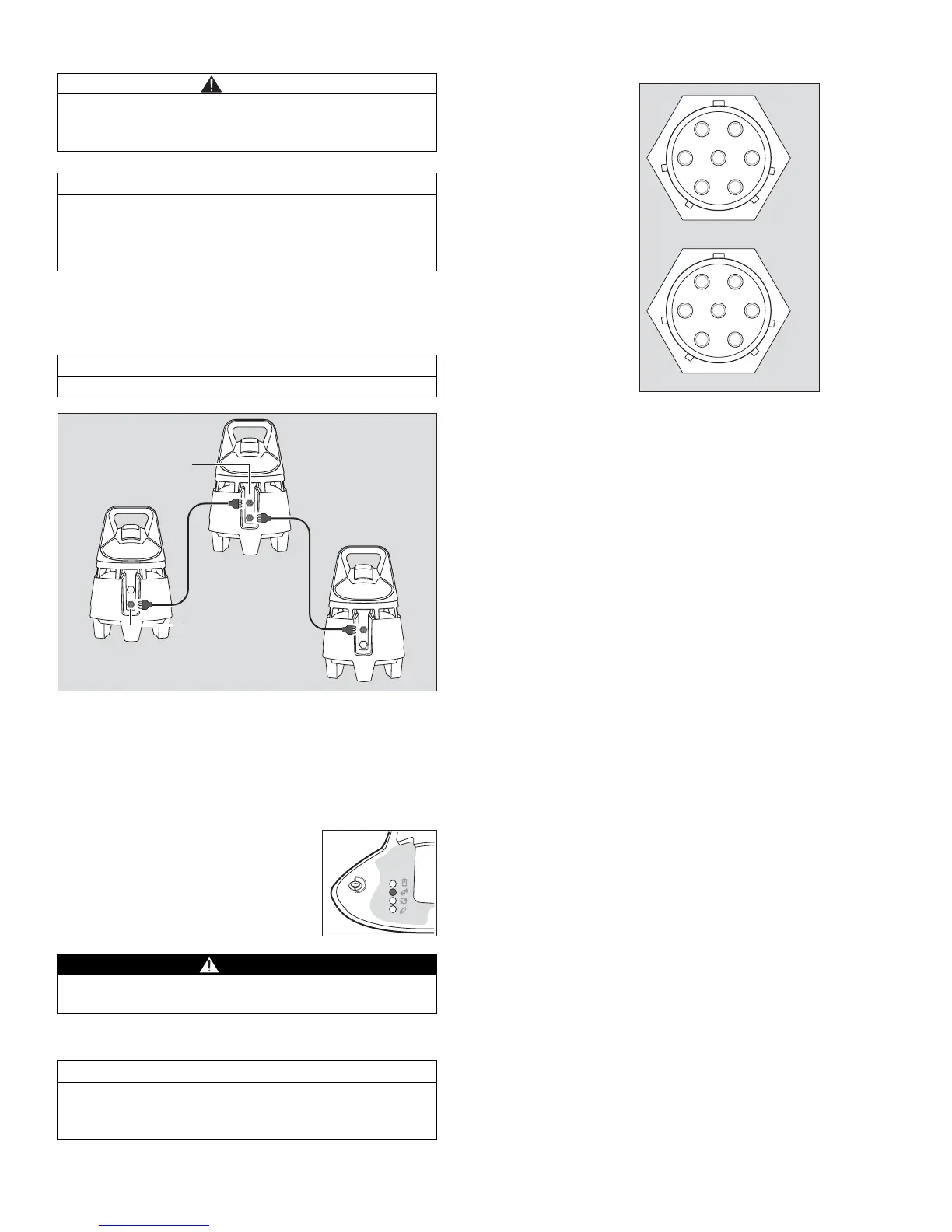
Connecting devices via a cable connection
If radio connections are not allowed or blocked, the
devices can be connected via communication cable.
The maximum cable length between two devices is
25 m.
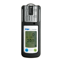
z Switching on Dräger X-zone 5000 (refer to
“Switching on the instrument” on page 5).
z
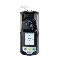
Plug the communication cable into the charging port/
RS485 connection (1) on the rear side of the device.
z Connect the end of the communication cable to the
switch relay/RS485 connection (2) of the second
device.
z If required, connect further devices via
communication cable as described above.
Pin configuration XEXT1 / XEXT2 on the device:
XEXT2 (male)
RS485
1 PLUS
2 MINUS
3 GND
Relay output
4 Normally Closed (NC)
5 Normally Open (NO)
6 Closed Only (CO)
7 GND
XEXT1 (female)
RS485
1 PLUS
2 MINUS
3 GND
Charger
4 Additional voltage (U-I
n
)
5 GND2
CAUTION
Before positioning the devices, a function test (refer to
“Perform a function test with gas” on page 7) must be
conducted on every device.
NOTICE
Due to widely differing customer-specific requirements,
Dräger does not provide any communication cables. All
relevant cable parameters are described in this
chapter.
NOTICE
Combined wireless and cable operation is possible.
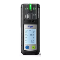
– The data transmission LEDs of the
coupled devices light green.
WARNING
If the data transmission LED is lit in red, check the
cable connection.
NOTICE
Dräger recommends performing a function test (refer to
“Perform a connection test” on page 7) after positioning
all the devices.