Commissioning
27
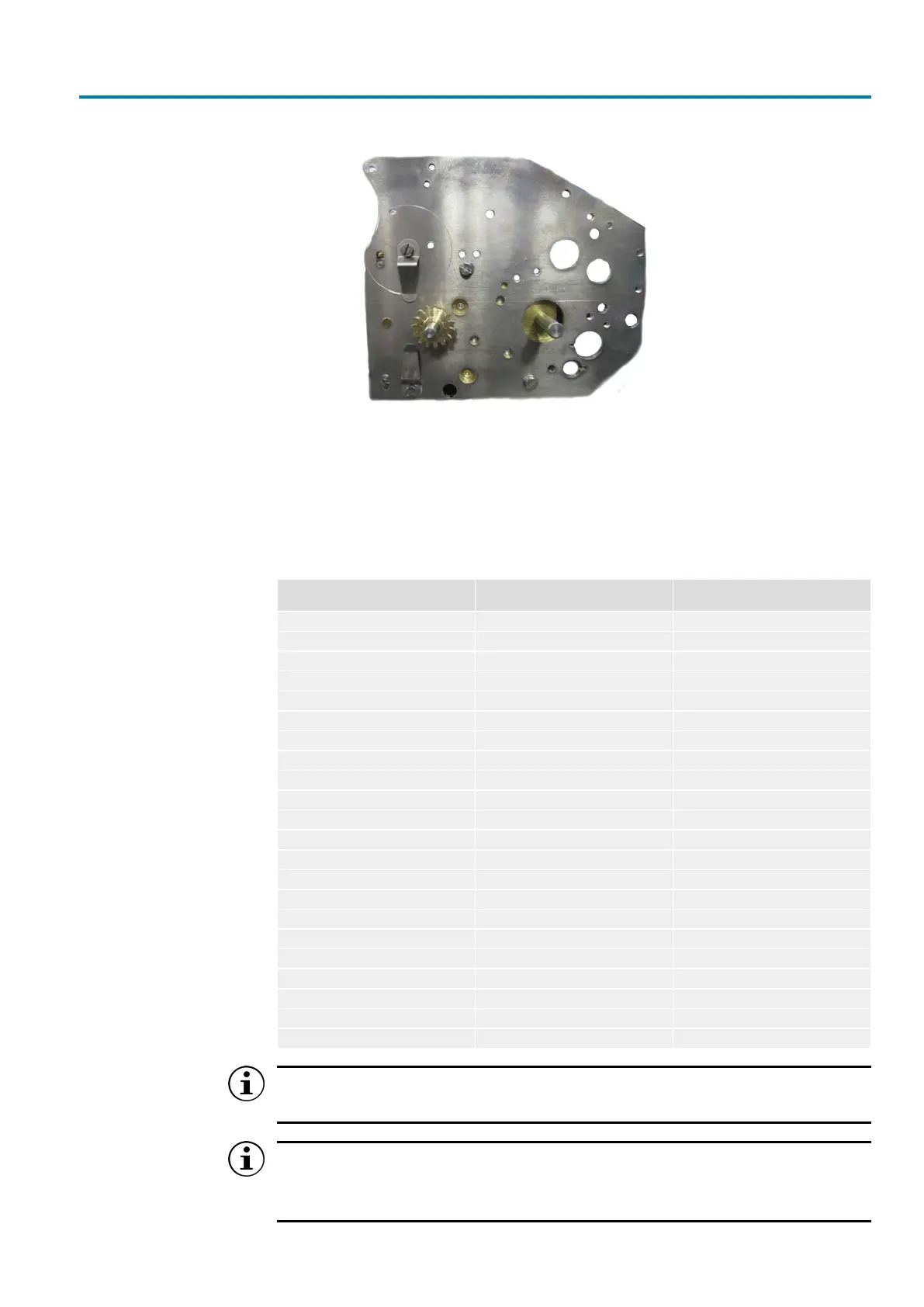
Figure18: Drive pinion
The reduction gearing is available for a range between 1.38 and 1,450 turns per
stroke (turns/stroke). The range is divided into two sections: III (1.38 – 135turns/
stroke, large gear wheel on small gear wheel) and II (12.4 – 450 turns/stroke; small
gear wheel on large gear wheel). Changing between these ranges requires exchan-
ging the gear wheels on the base of the limit switch base. By moving the sliding gear
wheel in one of the positions 4 – 11, the required travel range can be selected.
Table6: Setting options for the reduction gearing for multi-turn actuators
Transmission ratio of limit switch
wheels
Turns per stroke (min. and max.) Position of the sliding gear wheel
1:3 (section III) 1
1:3 (section III) 2
1:3 (section III) 3
1:3 (section III) 1.38 – 2.49 4
1:3 (section III) 2.5 – 4.5 5
1:3 (section III) 4.6 – 8.2 6
1:3 (section III) 8.3 – 15 7
1:3 (section III) 15.1 – 27.2 8
1:3 (section III) 27.3 – 49.6 9
1:3 (section III) 49.7 – 90.1 10
1:3 (section III) 90.2 – 135 11
3:1 (section II) 1
3:1 (section II) 2
3:1 (section II) 3
3:1 (section II) 12.4 – 22.4 4
3:1 (section II) 22.5 – 40.8 5
3:1 (section II) 40.9 – 74.2 6
3:1 (section II) 74.3 – 135 7
3:1 (section II) 135 – 245 8
3:1 (section II) 246 – 446 9
3:1 (section II) 447 – 811 10
3:1 (section II) 812 – 1450 11
The values of the sliding gear wheel positions 1 – 3 are available on request.
Preferably use the marked setting ranges.
Default setting unless ordered otherwise!
a) For output speed of 5 – 50 rpm, the factory setting is section III.
b) For output speed of 80 – 160 rpm, the factory setting is section II.