Commissioning
28
How to proceed During setting, proceed as follows:
1. If the desired turns/stroke ratio was available on delivery, the actuator has been
correctly set in the factory.
2. Determine output rotations per travel (e.g. output speed per minute multiplied by
operating time in minutes).
3. Determination of section II or III set in the factory. Determine output speed (e.g. by
name plate designation on the actuator name plate e.g. D60A-40 = 40rpm).
Section III set: Actuators with output speed 5 – 50rpm
Section II set: Actuators with output speed 25 – 160rpm
Alternative determination:
Move sliding gear wheel [3] to position 1. Apply approx. 13 handwheel turns while ob-
serving the mechanical position indicator (if available) or the cams of the intermediate
position switches. If the rotation angle detected exceeds 150°, section III has been set,
otherwise section II.
4. Setting the reduction gearing according to the calculated value by re-positioning
the sliding gear wheel in accordance with the Setting the reduction gearing for
multi-turn actuators [}27] table.
7.5
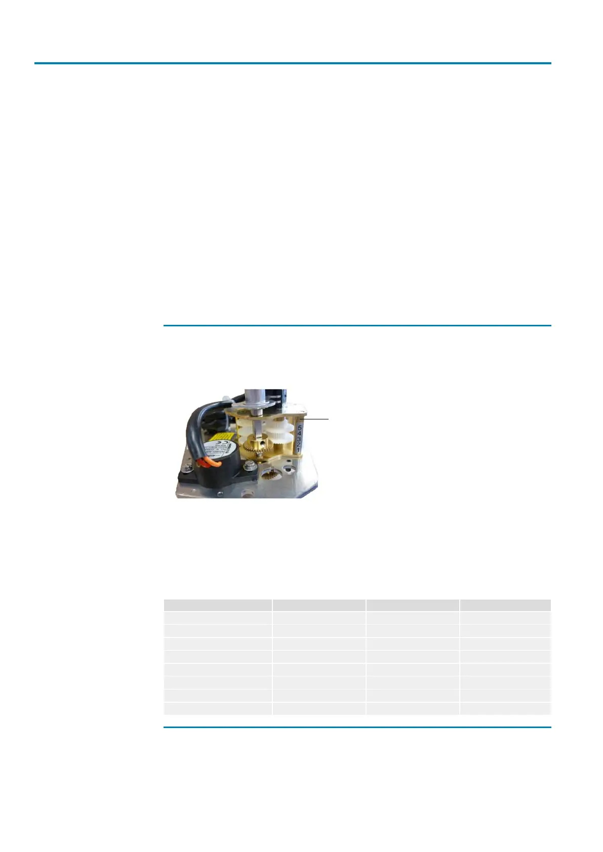
Setting the reduction gearing for part-turn actuators
The limit switching module includes a five-stage reduction gearing.
Figure19: Limit switching module DP 30 – 1800
Five-stage reduction
gearing
The reduction gearing has a variable setting range, resulting from the plug-in se-
quence of the gear wheels at the bottom of the mounting plate. The sections II (small
on large gear wheel) + III (large on small gear wheel) can be respectively preselected
by exchanging the gear wheels on the bottom of the limit switching base plate. For
section I, use two gear wheels of identical size. The setting options of this reduction
gearing are specified in the following table.
Table7: Setting options for the reduction gearing for part-turn actuators
Additional gearing SQ SQ SQ
Size DP600 – DP900 DP1200 – DP1800
Swing angle 90° 90° 90°
Reduction ratio 5.5 11 25.3
Number of teeth LS module I/30:30 II/45:15 II/45:15
turns/strokemin 1.375 2.75 6.325
Sliding gear wheel position 2 1 2
Turning angle α cam shaft 177.5 214.5 271.3
Modulation in % 59.1 71.5 90.4
7.6
Setting the mechanical position indicator
The figure below shows the components of the mechanical position indicator.