Limit switching module
22
6
Limit switching module
In this chapter, the limit switching module used in DREHMO actuators is described.
The limit switching module is located below the housing cover. The housing cover can
be removed by unfastening the four outer screws.
Depending on the actuator version, the illustrations of the respective components may
deviate from the standard or explosion-proof version. The actuator version can be
identified by the components used.
6.1
Design of the limit switching module
The limit switching module records limit positions and torques. In addition, it can be
equipped with mechanical and/or electronic elements to display the valve position.
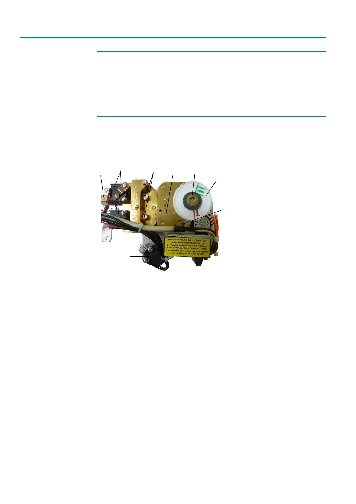
The illustration below shows a typical version.
Figure13: Limit switching module D(R)30 – 2000 in standard version
[1]
[2]
[3]
[4]
[5] [6]
[7]
[8]
[9]
[10]
[1] Torque switches [2] Heating resistor
[3] Limit switches [4] Adjustment screws for limit positions
[5] Mounting position of limit switches for
intermediate positions
[6] Adjustment screw for optional interme-
diate position signal
[7] Mechanical position indicator [8] Transit screw
[9] Potentiometer [10] Measuring amplifier
The torque and limit switches are operated via adjustable cams and are also available
as tandem switches as an option. For torque switches, labels are fixed to the cams in-
dicating the permissible setting range.
A measuring amplifier converts the potentiometer position into an analogue position
signal between 4 – 20mA. The potentiometer is limited to an angle of 270°. Therefore,
it is driven by a reduction gearing (please refer to Setting the reduction gearing for
multi-turn actuators [}27] oder Setting the reduction gearing for part-turn actuators
[}28] for the required gearing settings in relation to the respective travel).
In the factory, the potentiometer is set to valve position CLOSED and secured by
means of the transit screw. To maintain the potentiometer rotary range, the driving
pinion for the potentiometer is equipped with a slip clutch. As an option, a mechanical
position indicator can be fitted to the same shaft as used for the potentiometer pinion.
The position indicator must be adjusted in compliance with the set travel to report cor-
rect valve position.
In addition to the components described, a blinker transmitter is available as an op-
tion. The blinker transmitter is fitted to the lower side of the assembly plate and driven
by a disc. This allows for a blinking actuator operation signal.