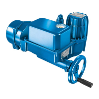
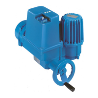
Commissioning
26
dicator, slightly loosen the transit screw (refer to Setting the mechanical position indic-
ator [}29]). After cam setting, fasten the screw (not too tight! Do not exceed 0.5 –
0.7Nm). Check the set tripping points by operating over full valve stroke.
7.4
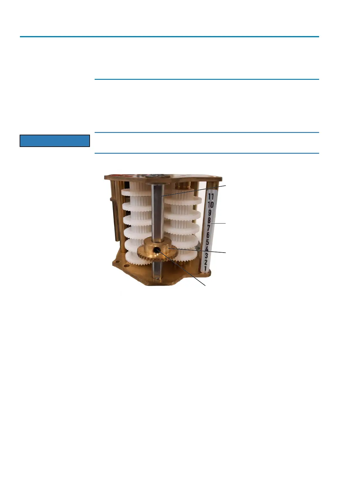
Setting the reduction gearing for multi-turn actuators
To re-set the reduction gearing, loosen the fastening screw and retain the shaft. After
unfastening the screw, the sliding gear wheel can be moved up (smaller angle for the
mechanical position indicator) or down (larger angle for the mechanical position indic-
ator). Once the new position of the sliding gear wheel has been reached, tighten
fastening screw again.
NOTICE
Heed correct position of the sliding gear wheel!
à The splines of the sliding gear wheel must fully engage into the counterwheel.
Figure17: Reduction gearing
[1] Shaft of the mechanical position indic-
ator
[2] Scale with possible positions
[3] Sliding gear wheel [4] Fastening screw
On the bottom of the mounting plate, the limit switching module is equipped with a
driving gear. The variant for section III is shown in the illustration below. For section II,
a larger gear is installed instead of a small one. The counter gear is mounted on a
shaft within the actuator.