COOLING SYSTEM SECTION 6
Page 9
DRESSTA TD-25M EXTRA
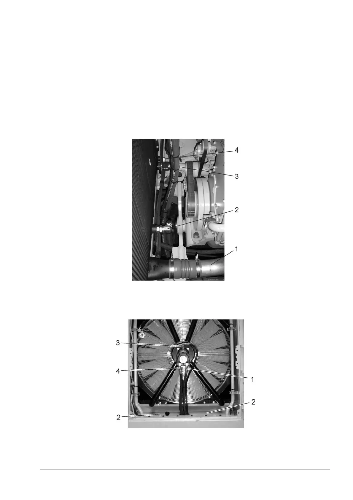
19 Loosen the clamps and remove tube (1, Fig. 6.5) from the cooler (CAC) and engine intake
manifold.
20. Remove hydraulic hose (2) from drive train oil cooler. Secure hose in an upright
position to frame.
NOTE: Small quantity of oil from drive train oil cooler should be drained to the suitable container.
21. Loosen the clamps and remove coolant outlet tube (2, Fig. 6.5) from the radiator and engine
inlet.
22. Tag and remove fuel hose (4) from the fuel cooler. Secure hose in an upright
position to frame.
NOTE: Small quantity of fuel from fuel cooler should be drained to the suitable container.
Fig. 6.5. Radiators Assy Connections (lower)
1. Air Outlet Tube (CAC outlet)
2. Hydraulic Hose (inlet)
3. Coolant Tube (outlet)
4. Fuel Hose (inlet)
Fig. 6.6. Fan Drive Hydraulic Motor Disassembly Points
1. Hydraulic Hose (inlet)
2. Air Baffles
3. Hydraulic Hose (drain)
4. Hydraulic Hose (outlet)
 Loading...