COOLING SYSTEM SECTION 6
Page 13
DRESSTA TD-25M EXTRA
9. INSTALLATION
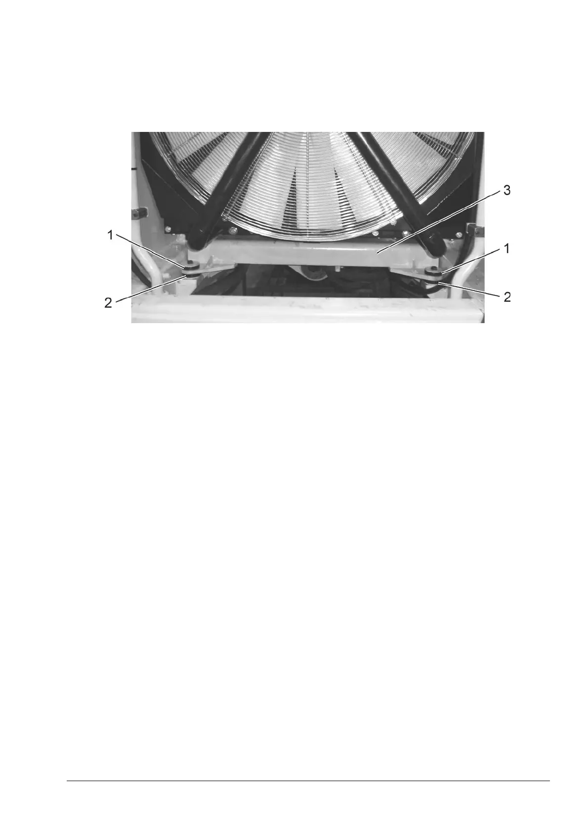
NOTE: Before mounting radiator assy remove bolts and washers (1, Fig. 6.10) and inspect rubber
shock absorber (2) of radiator channel (3) for wear.
Fig. 6.10. Radiator Assy Lower Bracket (front view)
1. Bolts and Washer
2. Rubber Shock Absorber
3. Radiator Assy Channel (bracket)
1. Use the slings to lift the radiator. Wrap the slings around the radiator bottom plate
and carefully hoist the radiator assy up and over frame. Position radiator assy on the
channel and install bolts (1, Fig. 6.8) securing assy to channel (2) at the bottom initially.
IMPORTANT: Do not use the hydraulic motor bracket for radiator assy hoisting.
2. Reinstall brackets (3, Fig. 6.7) to frame with the bolts. Install plate (2) linking two brackets with
the bolts (1) Tighten bolts securing the radiator assy to the bottom channel. Remove lifting
slings.
3. Reinstall hydraulic hoses (1, 3 and 4, Fig. 6.6) to the fan drive hydraulic motor.
4. Reinstall fuel hose (4, Fig. 6.5) to the fuel cooler.
5. Reinstall coolant tube (3) to the radiator and engine inlet. Tighten the clamps.
6. Reinstall hydraulic hose (2) to the drive train oil cooler.
7. Reinstall tube (1) to the air cooler (CAC) and engine intake manifold. Tighten the
clamps.
8. Reinstall fuel hose (2, Fig. 6.4) to the fuel cooler.
9. Reinstall hydraulic hose (1) to fan drive hydraulic motor oil cooler.
10. Reinstall tube (1, Fig. 6.3) to the air cooler (CAC) and engine turbocharger. Tighten the
clamps.
11. Reinstall coolant tube (4) between the radiator and engine outlet. Tighten the clamps.
12. Reinstall hydraulic hose (6) to fan drive hydraulic motor oil cooler.
13. Reinstall hydraulic hose (2) to the drive train oil cooler.
14. Reinstall coolant fill hose (3) to the auxiliary tank. Tighten the clamp.
15. Reconnect wire harness connector to the coolant level switches (6, Fig. 6.3) and (3, Fig. 6.7).
 Loading...