SECTION 13 SUPERSTRUCTURE
Page 4
TD-25M EXTRA DRESSTA
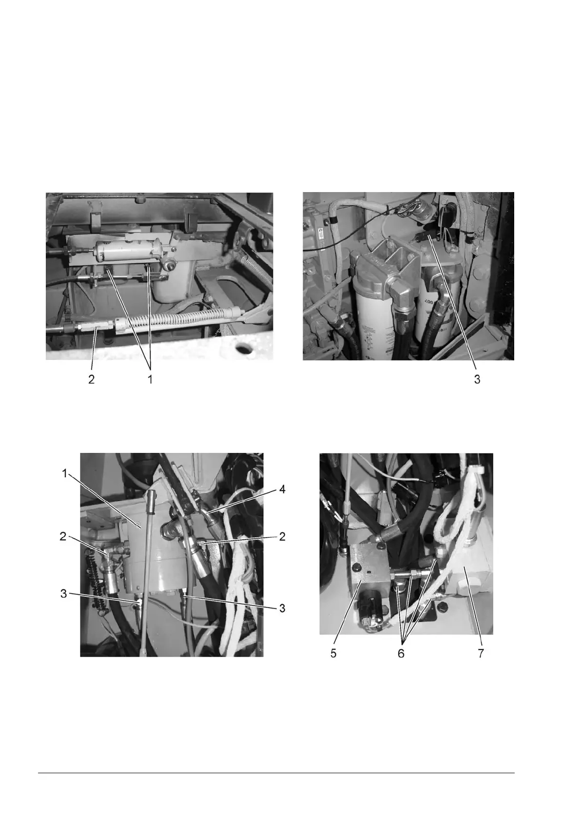
8. Tag and remove the hoses (6, Fig. 13.5) from the pilot lock valve (5) and switching valve (7).
NOTE: When disconnecting hydraulic lines for any reason, they should be properly capped with
correct size plastic cap. If these caps are not available, tape or clean rubber corks may be used.
Hydraulic openings must never be plugged with rags. This practice could easily introduce dirt or lint
into critical hydraulic components of machine. Tag all disconnect oil lines to facilitate installation.
9. Tag and remove the hoses (2, 3 and 4) from the drive train control valve. Remove the frame on
the bottom of console. Pool the hoses down from console.
Fig. 13.4. Disassemble Points Under the Pod
1. Wiper Washer Tanks
2. Brake Control Cable
3. Engine Control Potentiometer Plug
Wire Harness Plug
Fig. 13.5. Lock Valve and Control Valve Disconnecting Points (LH console)
1. Drive Train Control Valve
2. Hoses (steering control)
3. Hoses (forward – rear)
4. Hose (Drain)
5. Pilot Lock Valve
6. Hydraulic Hoses
7. Switching Valve
 Loading...