SUPERSTRUCTURE SECTION 13
Page 5
DRESSTA TD-25M EXTRA
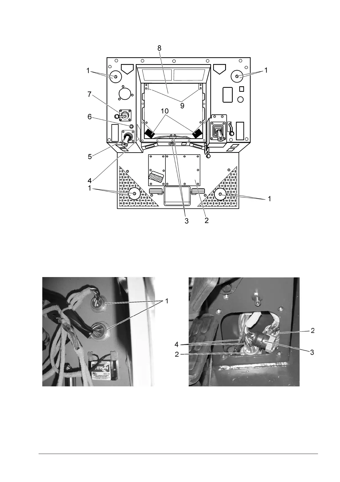
Fig. 13.6. Pod Assy Disassembly Points
1. Bolt and Plate
2. Floor Plate
3. Master Switch
4. R.H. Console Cover
5. Blade Control Pilot Valve
6. Horn Push Button
7. Ripper Control Pilot Valve
8. A/C Heater Assy
9. Conditioner Mounting Hardware
10. Air Hoses
Fig. 13.7. LH Console and Instrument Panel Column electrical Connections
1.Wire Harness Sockets 3. Engine Data Link Connector
2. Wire Harness Plugs 4. Instrument Panel Supply and Ground Cables
10. Remove wire harness plugs from the sockets (1, Fig. 13.7).
 Loading...