TRACKS OR WHEELS SECTION 15
Page 15
DRESSTA TD-25M EXTRA
TRACK CHAIN
2. To replace a damaged section of track, remove the track shoes, and cut out the damaged
section with a cutting torch. Remove the end links as outlined in the following Step 3. Rebuild
the section onto the track by pressing individual links, link pins and bushings together with
a hydraulic track press using the installing tool with necessary adapters listed in Fig. 15.10.
3. To replace an individual link that is damaged, remove the track from the machine. After the track
is free and extended flat, remove three or four of the track shoes adjacent to the damaged part.
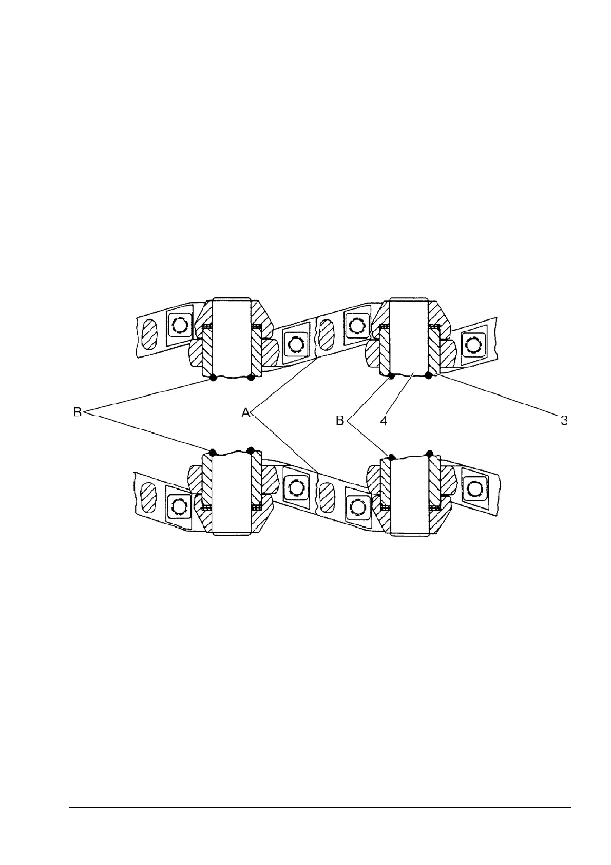
Cut the pins and bushings of the damaged link with a torch. The cuts should be made as close
to the inside faces of the inner links as possible (Fig. 15.18) to provide sufficient clearance
between the links for the removal of the remaining pin and bushing sections.
IMPORTANT: Be careful not to damage the inner faces of the links when cutting the bushings and
pins.
Fig. 15.18. Removal of Damaged Links
3. Bushing
4. Pin
A. Broken Link or Links to be Replaced
B. Torch Cut and Weld Pins and Bushings at Each End of Broken Links
4. The pieces of the pins and bushings remaining in the links must now be securely welded
together at the cuts (Fig. 15.18). It is important that the welds be strong enough to carry the
bushing out with the pin. Press each of the pin and bushing assemblies (welded) out of the
links. Remove the sealing washers from the link counterbore.
5. Remove and replace the damaged link or links. Assemble the two loose, right and left, track
links using a bushing (Fig. 15.19). Assemble a bushing also into the links attached to the track
(Fig. 15.19). Place the spring seal washers and bushing spacers into the link counterbore
(Fig. 15.19). Place the bushing and links assembly onto the track and insert the aligning pin to
hold the track link alignment while the new pin is pressed in position (Fig. 15.19). Use the
aligning pin again when joining the two sections of track.


 To Next Page