Installation and Wiring
7
SECTION 1 2 3 4 5 6 7 8 9 10 11 12 13 14 15 16
Typically, this output is used for providing power to latch-
ing type devices that require a power interruption in order
to reset.
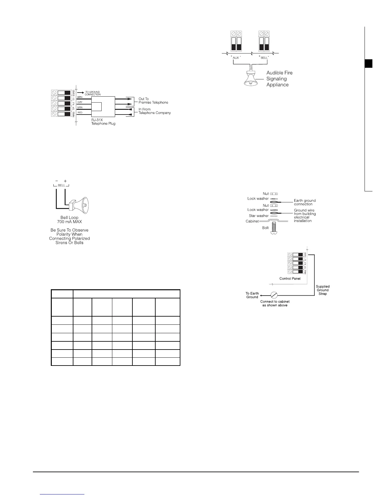
2.11 Telephone Line Wiring
The telephone terminals provide connections to the
incoming telephone lines for central station reporting. The
wires from the RJ-31X jack must be connected in the fol-
lowing manner:
NOTE: There must be no other telephone equipment
connected between the control panel and the incom-
ing telephone line (e.g. answering machines, fax
machines, telephones, etc.). Ensure that plugs and
jacks meet the dimension, tolerance and metallic plat-
ing requirements of 47 CFR Part 68 Subpart F.
2.12 Bell Output Wiring (BELL
+
and BELL
-
)
These terminals are used for powering
bells, sirens or other devices requiring
steady output voltage on alarm. The
panel can provide up to 2A short-term
or 700mA long-term current. The out-
put is supervised. A trouble condition
will be generated when the bell con-
nection is lost. If no bell or siren is
being used, connect a 1000Ω resistor
across the BELL+ and BELL- terminals
to eliminate a trouble condition.
To ensure proper operation, the wire length of the bell
loop must be considered.
Consult the following chart to determine the maximum
wire length for the bell loop with respect to current. The
values reflect the use of a 30 watt siren.
To increase the length, double up on wire. For example,
when using 22-gauge quad, use two conductors for the
Bell+ connection and two for the Bell-. This effectively
doubles the maximum distance.
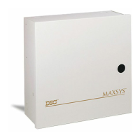
For UL residential installations, when a bell or siren is
used for fire signaling with a pulsed cadence, it must be
connected between the AUX+ and BELL- terminals. To
maintain bell circuit supervision, do not connect more
than one device to the BELL- terminal. A fire bell or siren
used for this application must be UL Listed and have a
current consumption of 400mA or less (e.g. Wheelock
MT-12/24-R).
NOTE: For Commercial Fire applications, you must use
the ‘CF’ version of the panel and the PC4702BP.
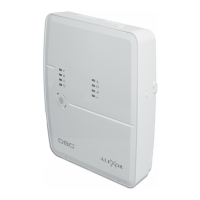
2.13 Earth Ground Wiring
The cabinet should be earth grounded using the ground-
ing kit supplied. Ensure that the connection from the cabi-
net to the metallic cold water pipe or earth grounding rod
is made with minimum 14-gauge solid copper wire.
The EGND terminal must be connected to earth ground to
enable ground fault detection. A Ground Fault trouble
will be indicated if any conductor on the system has a
resistance to earth ground of 40kΩ or less.
Only earth ground the main panel and the first module
connected to the telephone line.
2.14Applying Power (AC and Battery)
WARNING: Do not connect the battery or transformer
until all other wiring is complete.
Battery Connection – Red & Black Battery Leads
Connect the red battery lead to the positive terminal of the
battery and the black lead to the negative terminal.
WARNING: Observe the correct polarity. If the battery
is connected backwards, the panel will not operate.
AC Power Terminals
WARNING: Connect the battery before connecting the
AC.
A 16V, 40 VA transformer connected to an unswitched AC
power source should be wired to these terminals.
To achieve the rated outputs as previously described, the
AC input must be connected to the secondary of a trans-
former rated at 16 VAC, 40VA minimum. The transformer
is not supplied with the equipment and must be mounted
outside the cabinet.
Do not connect the transformer primary to an outlet that is
controlled by a switch.
Distance to last bell/siren (ft/m)
Bell Loop
Load
Current
22 AWG
Wire
20 AWG
Wire
18 AWG
Wire
16 AWG
Wire
14 AWG
Wire
2000mA 18/6 29/9 46/14 73/22 116/35
1800mA 20/6 32/10 51/16 81/25 129/39
1000mA 36/11 58/17 92/28 147/44 233/70
700mA 52/16 82/25 132/40 210/64 332/101
500mA 73/22 115/35 184/56 293/89 465/141
100mA 364/110 577/175 922/279 1467/445 2326/705
Tighten nut to break paint and make
good connection to the cabinet