2
Section 2: Installation and Wiring
2.1 Planning the System
The speed and efficiency of installing a MAXSYS system
will be greatly enhanced by planning the installation. As a
minimum, the following checklist should be used to
ensure that all of the details have been considered:
❑ Draw a diagram of the installation showing the loca-
tion of the main panel, all keypads, zone inputs, bell
outputs, relay outputs and annunciators.
❑ Indicate all partitions on the diagram. Decide which
zones, bell and relay outputs, keypads and remote
annunciators belong to each partition.
❑ Determine where each system module is going to be
located and how far each module will be from the
main panel.
❑ Determine the current draw on the main panel and
each system component used to ensure the system
requirements can be met (see 2.4 ‘Current Ratings –
Alarm Control Panel and Modules‘). Calculate each
wire run using the Combus wiring guidelines. Deter-
mine which wire gauge should be used and where to
place PC4204/PC4204CX modules to re-power the
Combus.
❑ For Addressable devices, determine where each device
is to be located and consult the Addressable Loop wir-
ing guidelines to determine wire gauge and wiring
lengths (see 2.9 ‘AML Device Wiring‘)
2.2 Terminal Descriptions
The following terminals appear on the alarm control
panel:
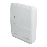
2.3 Wire Routing for Power and Non-Power
Limited
All wiring entry points are designated by the arrows. All
circuits are classified UL installation power limited except
for the battery leads which are not power limited.
A minimum ¼” (7mm) separation must be maintained at
all points between power limited and non-power limited
wiring and connections.
NOTE: Wire entry for power limited wiring must be
separated by a different entry access from non-power
limited wiring.
2.4 Current Ratings – Alarm Control Panel and
Modules
In order for the system to operate properly, the power out-
put of the alarm control panel and power supply modules
cannot be exceeded. Use the data below to ensure that the
available current is not exceeded.
Alarm Control Panel
AUX - 500mA available for devices connected to the AUX,
SAUX+ and PGM terminals and modules connected to
Combus terminals. At least 100mA must be reserved for
the Combus. To calculate the amount of current required,
complete the following chart:
Main Panel Current Calculation
Maximum (Standby or Alarm)
AUX (500mA max.)
SAUX+ (300mA max.)
Terminals Description
Red and
Black Leads
Battery Connection. WARNING: Do not con-
nect the battery or transformer until all
other wiring is complete.
AC Power Terminals. WARNING: Connect the bat-
tery before connecting the AC. Do not con-
nect the battery or transformer until all
other wiring is complete.
AUX+ and
AUX-
Auxiliary Power, 500mA MAX
SAUX+ Switched Auxiliary Power, 300mA MAX
BELL+ and
BELL-
Bell/Siren Power. These terminals are used for
powering bells, sirens or other devices requiring
steady output voltage on alarm; 700mA MAX
PGM1 and
PGM2
Programmable Output Terminals.
50mA MAX (standard output) or
170mA MAX (addressable loop)
RED, BLK,
YEL, GRN
Combus Terminals. The Combus is used by the
panel and the modules to communicate with
each other. RED and BLK are used for power, and
YEL and GRN for data. NOTE: The four Combus
terminals of the main panel must be con-
nected to the four Combus terminals or
wires of all modules. For instructions
regarding Combus wiring, refer to Section
2.4 ’Combus Operation and Wiring’.
Z1 to Z16 Zone Input Terminals. Zone inputs Z1 to Z16 are pro-
vided for wiring zones on the alarm control panel
TIP, RING,
T1, R1
Telephone Line Terminals
EGND Earth Ground Connection. A ground connection
assembly is included with the control panel.
Please refer to the control panel wiring diagram
for ground connection instructions.
Terminals Description
NOTE: A minimum 1/4" (6.4mm)
separation must be maintained at all
points between power limited & non-
power limited wiring and connections.