Installation and Wiring
3
SECTION 1 2 3 4 5 6 7 8 9 10 11 12 13 14 15 16
PGM1 (50/170mA max.*)
PGM2 (50/170mA max.*)
Combus (500mA max.)**
Total (must not exceed 500mA)
*PGM1/PGM2 (Standard Output) = 50mA max.
NOTE: PGM1/PGM2 (Addressable Loop) = 170mA max.
NOTE: To calculate Addressable Loop current, see 2.9
‘AML Device Wiring‘.
**See ‘Combus Current Calculation Chart’ below.
NOTE: For UL Listed applications, the total standby and
alarm current cannot exceed 900mA.
Module Ratings
The current draw of compatible modules is listed below:
Device.................................................Current Draw (mA)
Keypad (LCD45XX).........................................................50
PC4108A Zone Expander ............................................... 30
PC4116 Zone Expander................................................... 30
PC4164 Wireless Receiver............................................. 110
PC4701 Fire Module ........................................................ 35
PC4702BP Dual Bell Output Module............................ 75
PC4204 Relay Output Module....................................... 30
PC4204CX Combus Repeater......................................... 30
PC4216 Low Current Output Module .......................... 15
ESCORT4580 Audio Assistant..................................... 150
PC4401 Interface Module ............................................... 35
PC4820 Access Control Module .................................... 35
PC4936 Audio Interface Module................................... 65
PC4850 Module.............................................................. 135
Calculating Total Current Requirement
Once you have determined which modules will draw
power from the main panel, use the following chart to cal-
culate the Combus current.
NOTE: *These units draw current from the Combus to
power devices external to the module. This current must
be added to the total Combus current. See manufac-
turer's specifications for the current draw of each
device. Each LED assembly draws up to 20mA of current.
2.5 Combus Operation and Wiring
The Combus is used by the control panel and the modules
to communicate with each other. The four Combus termi-
nals of the main panel must be connected to the four Com-
bus terminals or wires of all modules.
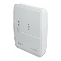
Modules can be home run, connected in a daisy chain or
T-tapped anywhere on the Combus.
The following rules MUST be followed when wiring the
Combus:
1. The Combus must be run in minimum 22-gauge wire.
2. No module can be more than 1000' (305m)
1000' (305m) 1000' (305m)
1000' (305m) in cable
length from the main control panel.
3. Shielded wire should only be used in areas that
present excessive RF noise or electromagnetic interfer-
ence. If shielded wire is used, the maximum distance a
module can be located from the main panel is signifi-
cantly reduced. Check the capacitance limit of the wire
to calculate the maximum distance (see ’Capacitance
Limits’ below).
4. The total capacitance of the Combus wiring must not
exceed 80nF (see ’Capacitance Limits’ below).
5. Do not run Combus wire runs in parallel with AML
wire runs. Maintain minimum 2” separation between
the cables.
Line Loss
When current is drawn through a piece of wire, voltage
will be lost due to the wire’s resistance. This voltage loss
must be considered for all installations.
To ensure proper operation, at least 12.5V
DC
must be
applied to all modules on the system (when AC is applied
and the battery is fully charged). If less than 12.5V
DC
is
applied, system operation will be adversely affected.
To correct the problem, try any or all of the following:
1. Connect a PC4204/PC4204CX power supply near the
module to provide power to the Combus.
2. Reduce the length of the Combus run to the module.
3. Increase the gauge of wire.
Combus Current Selection Chart
Item Current (mA) x Quantity Total (mA)
Keypad 50 x
PC4108A* 30 x
Current required for connected devices =
PC4116* 30 x
Current required for connected devices =
PC4164 110 x
PC4701 35
PC4702BP 75 x
PC4204/PC4204CX 30 x
PC4216* 15 x
Current required for connected devices =
ESCORT4580 150
PC4401 35 x
PC4820 35 x
Total Combus Current =
PC4850 135 x
PC4936* 65
T-Lin k 150
Skyroute 30
Combus Current Selection Chart
Item Current (mA) x Quantity Total (mA)
Total Combus Current =