33
Section 11: Programmable Outputs
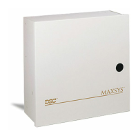
11.1 Main Panel Outputs
The main panel has four programmable outputs: Bell,
SAUX+, PGM1 and PGM2. Adding PC4216/PC4204/
PC4204CX/PC4702 modules can expand the number of
outputs. All outputs can be individually programmed to
activate according to any of the programmable output
options (listed in Section 11.2 ’Programmable Output
Options’).
SAUX+ Output
Ref #: [0005]
The SAUX+ output can supply up to 300 mA at 12VDC.
It can be programmed as one of the output options (see
11.3 ‘Programmable Output Options‘).
The default setting of this output is to provide switched
power for 4-wire smoke detectors (output option 39
Command Output #2, enabled for Partition 1 with a 5-
second pulse time). When used in this mode, the 12V
positive output is switched OFF to reset the smoke detec-
tors by using the [*][7][2] Command from the keypad
(’Reset’ function key on LCD4501 keypads).
Bell Output
Ref #: [0006]
The BELL+ terminal is always 13.8 VDC. The BELL- ter-
minal is normally 12.6 VDC. This voltage difference is
required for bell circuit supervision. When the bell out-
put is activated, the panel will switch BELL- to ground.
If the bell output is not being used, connect a 1000Ω
resistor across the BELL terminals to eliminate a trouble.
This output can be programmed for one of the available
output options (see 11.3 ‘Programmable Output
Options‘).
PGM Outputs
Ref #: [000700] for PGM1
Ref #: [000701] for PGM2
The PGM output terminals (PGM1 and PGM2) energize
when activated. If the inverted option is selected, the out-
put will de-energize when activated. Either output can be
programmed as one of the available output options (see
11.3 ‘Programmable Output Options‘).
The default setting for both outputs is Command Output
#1 (option 38), active on partition 1 with a 000 second
pulse time.
To program PGM 1 and/or PGM2 for AML devices, see
4.4 ‘Enrolling AML Devices‘. An output programmed for
AML use cannot also be assigned an output option.
11.2 Programming Programmable Output
Options for Modules
Ref #: [000702] for PC4204 modules
Ref #: [000703], [000704] for PC4216 modules
Ref #: [000705] for Escort4580 Automation Items
Ref #: [000707] for PC4702 module
Programming PGM output options for modules works
similarly to the programming for PGM1 and PGM2. Refer
to the Installation Instructions for each module for more
information.
The programming for the Escort4580 refers to automation
items and not actual output terminals on the module. See
the Escort4580 Installation Manual for a full description of
automation items, and how they work.
11.3 Programmable Output Options
There are 59 available options for outputs on the PC4020
v3.3 as well as the PC4204/PC4204CX/4216 output mod-
ules. Some options require that you select which partitions
will activate the output. Use the [<] [>] keys to scroll
through each partition and press [*] to toggle each partition
on and off.
Fire and Burglary (00)
The output will activate when any fire or burglary alarm
occurs on any of the selected partitions.
Inverted Fire and Burglary (01)
The output will deactivate when any fire or burglary alarm
occurs on any of the selected partitions.
Burglary Only (02)
The output will activate when any burglary alarm occurs
on any of the selected partitions.
Inverted Burglary Only (03)
The output will deactivate when any burglary alarm occurs
on any of the selected partitions.
Fire Only (04)
The output will activate when any fire alarm occurs on any
of the selected partitions.
Inverted Fire Only (05)
The output will deactivate when any fire alarm occurs on
any of the selected partitions.
Arm Status (06)
The output will activate when any of the selected partitions
are armed.
Inverted Arm Status (07)
The output will deactivate when any of the selected parti-
tions are armed.
Date Schedule (08)
The output will perform according to a selected date sched-
ule. Enter a date schedule number from 02-99. In addition,
enter a pulse time from 00-59 seconds. Programming [00]
will cause the output to activate for the entire schedule. To
program date schedules, see 14.1 ‘Date Schedules‘.
Latched Strobe (09)
The output will activate when any alarm occurs on any of
the selected partitions. The output will stay activated until
the partition that caused the alarm is disarmed. If disarmed,
the output will stay active until the partition is armed.
Trouble Output (10)
The output will activate when a trouble condition is present
on any of the selected partitions. If a system trouble occurs
(e.g. loss of time, TLM trouble), all trouble outputs will acti-
vate for all partitions.
Courtesy Pulse (11)
The output will activate during exit or entry delay and for
an additional two minutes on any of the selected partitions.
It will also activate upon disarming if the partition is armed
without entry delay.
Chime Follower (12)
The output will activate when the door chime is activated
on any of the selected partitions The output will deactivate
when the chime pulse timer expires (see 11.4 ‘Output Pulse
Times‘).
Door chime activates when a zone with the Chime attribute
enabled is opened and activates again when the zone is