UL Listed Commercial and Residential Installations
The installation requirements listed below must be met for the following grades of service.
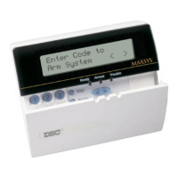
Note: All modules, keypads and enclosures used with this control panel must be UL Listed/Labeled.
Grade AA Central Station and Police Connect
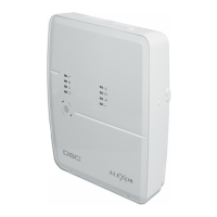
The installation must use T-Link module which communicates over
LAN/WAN to the Sur-Gard MLR-IP receiver. Polling time must be
90 seconds. Compromise detection time must be 6 minutes.
Grade A Local
The installation must have a bell UL Listed for mecantile local alarms
(AMSECO MBL10B with Model AB-12 bell housing).
The digital communicator must be enabled.
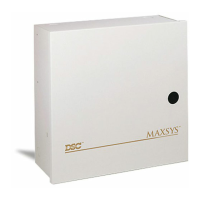
The control panel must be in the Attack Resistant Enclosure (UL Listed
DSC models CMC-1, PC4004C, P/PC4050CAR or P/PC4050CRAR).
Grade B Central Station and Grade A Police Connect
The installation must have a bell UL Listed for mecantile local alarms
(AMSECO MBL10B with Ademco AB-12 bell housing).
The digital communicator must be enabled.
The control panel must be in the Attack Resistant Enclosure (UL Listed
DSC models CMC-1, PC4004C, P/PC4050CAR or P/PC4050CRAR).
Grade C Central Station
The digital communicator must be enabled.
The control panel must be in the Attack Resistant Enclosure (UL Listed
DSC models CMC-1, PC4004C, P/PC4050CAR or P/PC4050CRAR).
All Commercial Installations
• The entry delay must not exceed 60 seconds
• The exit delay must not exceed 60 seconds.
• The minimum bell cutoff time is 15 minutes.
Residential Installations
• The entry delay must not exceed 45 seconds
• The exit delay must not exceed 60 seconds.
• The minimum bell cutoff time is 4 minutes.
Programming
The notes in the programming sections describing the system config-
urations for UL Listed installations must be implemented including
the following:
• The ‘Quick Exit’ feature must be disabled.
• The ‘Bell Squawk on Trouble’ feature must be enabled.
• The minimum ‘Dialing Attempt’ is five and maximum is ten.
• All Burglary-type zones should be configured with EOL configu-
ration.
• The ‘Code Required to Bypass zones’ feature must be enabled.
• Select ‘Bypass Status Not Displayed While Armed’ option.
• ‘Test Transmission Cycle’ must be set for daily transmission.
• ‘Temporal Three Fire Signal’must be enabled.
• Keypad Lockout’ must be programmed.
• ‘Closing Confirmation’ must be enabled.
• ‘Trouble Light Flashes If AC Fails’ option must be enabled.
Control of the Protected Premises
In order to have a UL Certificated system the protected area is to be
under the responsibility of one ownership and management (i.e. one
business under one name). This may be a group of buildings
attached or unattached with different addresses but under the
responsibility of someone having mutual interest. The person of
mutual interest is not the alarm installing company.
Bell Location
The alarm sounding device (bell) must be located where it can be
heard by the person or persons responsible for maintaining the secu-
rity system during the daily arming cycle.
Protection of the Control Unit
The local control and the local power supply must be protected by
one of the following ways:
• The control unit and audible alarm device must be in a protected
area which is armed 24 hours a day.
• Each partition shall arm the area protecting the control unit and
the audible alarm device power supply. This may require dupli-
cate protection armed by each partition. Access to this protected
area, without causing an alarm, will require that all partitions be
disarmed.
In all cases described above, the protected area for the control unit
must be programmed as not bypassable.
User Information
The installer should advise the users and note in the user instruction
manual:
• Service organization name and telephone number
• The programmed exit time
• The programmed entry time
Commercial Fire Monitoring Installations
• Refer to Commercial Fire Installation Guide