3
Section 2: Quick Start
2.1 Installation
1. Determine the Operating Mode Required
The operating mode (Modes 1, 2, 3, Standard Mode, or DVACS Mode) will determine how the
unit is to be wired.
2. Determine the Mounting Location
Select a mounting location in a dry, protected area at least 30 cm. away from physical contact
with any person. Refer to page 34, appendix C, for Network Protection details.
NOTE: Do not exceed the following recommendations for wire run distances
• Input wiring should must be minimum 22 gauge quad (0.5mm). Two pair twisted is pre-
ferred.
• PC5108, or zone wiring must not exceed 1,000' (305m) (in wire length) from the T-Link
module.
• Shielded wire is not necessary unless wires are run in an area that may present excessive
RF noise or interference.
• Refer to section 9, Programming Descriptions, section [36] for zone wiring details.
3. Route Wiring to Mounting Location
Route wiring from the hard wired zones or control panel as required.
NOTE: Route wiring through conduit to a junction box if possible.
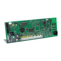
4. Mount the T-Link TL250/300 Panel
2.2 Testing
Mode 4, Standard Mode: Ensure the panel is programmed to use the T-Link TL250 in accor-
dance with the settings outlined in section 8, Programming Guide. Simulate Burglar and Fire
Zone violation on the DSC alarm panel. Verify that the T-Link TL250 transmits the events to
the central station.
Mode 1: Ensure the T-Link is programmed in accordance with the settings outlined in Sections
9, Programming Descriptions. Simulate Burglar and Fire Zone violation on the alarm panel.
Verify that the T-Link TL250 transmits the events to the central station.
Modes 2, 3 and 5 (DVACS): Simulate Inputs violations in accordance with the settings out-
lined in Sections 9, Programming Descriptions. Verify that the T-Link TL250 transmits the
events to the central station.
TL300 Simulated Phone: Ensure the T-Link TL300 Input 1 is programmed in accordance
with the TL300 settings outlined in Sections 9, Programming Descriptions. Simulate Burglar
and Fire Zone violation on the alarm panel. Verify that the T-Link TL300 transmits the associ-
ated Contact ID code to the central station.

 Loading...