11
Section 7: TL300 Telephone Simulation
7.1 TL300 Panel Installation.
• Secure the T-Link module to the side of the cabinet of the control panel or install the T-Link TL300
in a DSC enclosure (model PC5003C). Refer to Appendix B: T-Link TL300 Compatibility Chart
for a list of panels supported
• With AC power and battery disconnected removed from the control panel, connect the T-L300 to
the RJ31 phone jack from the panel to the RJ31 connector on the T-Link.
• Wire the panel's 12V
DC and GND terminals of T-Link or Power unit with a 12VDC 225 mA UL
Listed Power supply.
• Wire the panel's Tip and Ring terminals to the T1 and R1 terminals of T-Link TL300.
• Apply AC and DC to the main control panel. Both the T-Link and the panel should power up.
• Do the necessary programming that is required.
7.2 T-Link TL300 Operation
Communication events between the panel, T-Link and the Central Station receiver are as follows:
• When an alarm triggers, the panel goes off-hook
• The T-Link module sends a dial tone to the panel
• The Panel dials the telephone number of the central station
• The T-Link detects the DTMF dialing and stops sending the dial tone.
• The T-Link sends a request to the Receiver.
• The Receiver responds with the command to the T-Link to generate the corresponding handshake.
• After receiving the handshake, the Panel transmits the alarm message in DTMF Contact ID format
• The T-Link decodes and transforms DTMF digits into an IP packet and sends it to the Receiver
over IP.
• The Receiver acknowledges alarm and sends command to the T-Link to generate a corresponding
kiss-off signal.
• After the T-Link generates kiss-off, the Panel goes on-hook if no more alarms need to be sent.
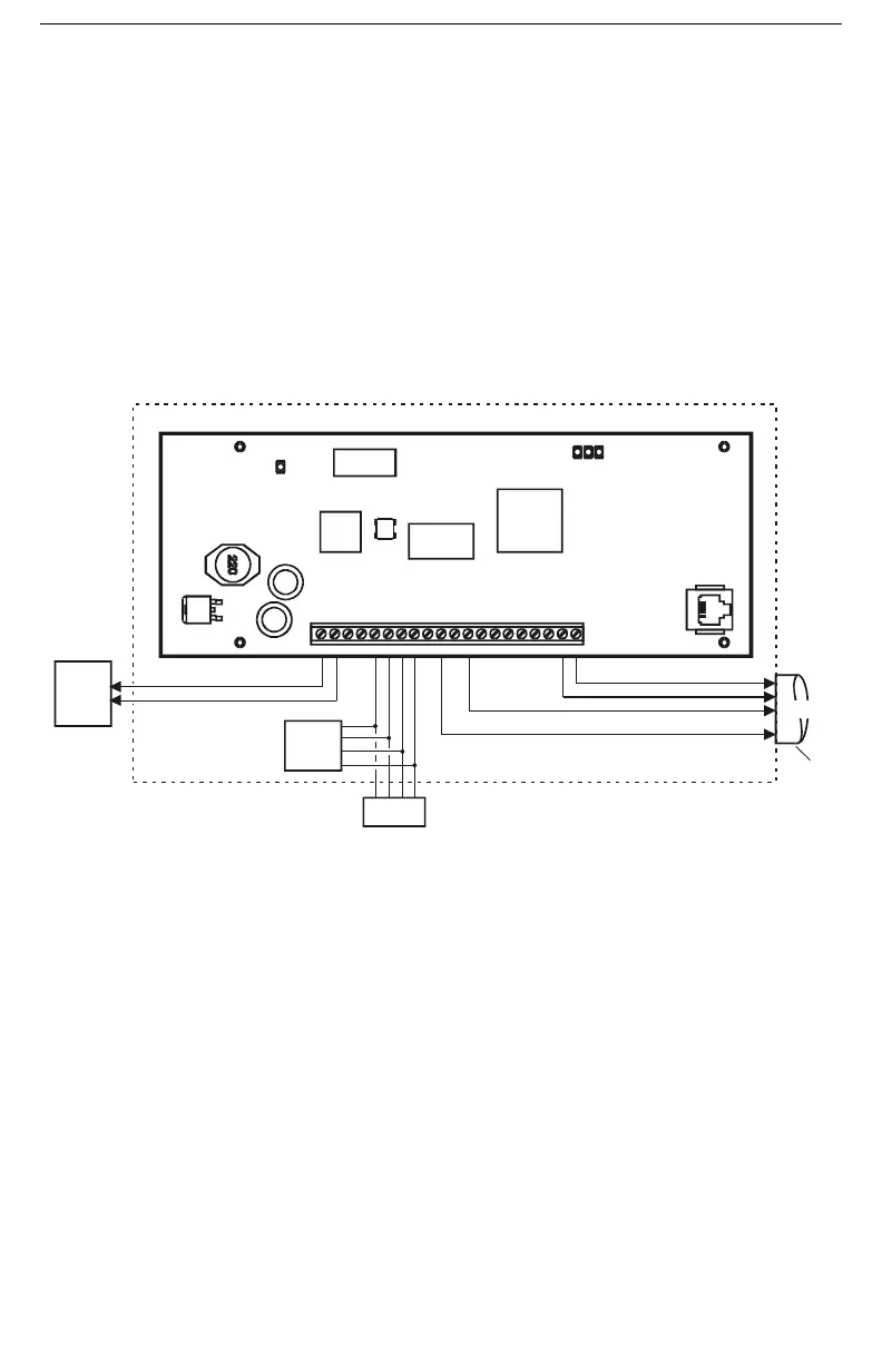
CON5
SPD ACT LNK
STAT
+12 V GND TX RX G ND R ED BL K YE L G RN P GM 1 PGM 2 IN1 G ND IN2 IN3 GN D IN4 E ARTH T1 R1
T-Link TL300
Connect PGM1 to panel zone to indicate network loss configure as TLM or FTC
(Refer to alarm pan el manufactur ers documentation)
Note: Do NOT con nec t the alarm panel or T-link TL300 to telephone line
Temporary connection of Keypad for programming
of T-Link during first 30 secon ds of power up shown
Configure zone as zone definition 98 (see section [036]-[047] Option [98]
To Tip and Ring on Alarm Panel
12V 360mA
UL Listed
Power Supp ly
or
Panel Aux
12VDC
PC5108
(optional)
LCD5500
Keypad
PC5003 Cabinet
Metal Conduit
20 ft(6m) max
Connect to
Alarm Panel

 Loading...