1
Section 1: Introduction
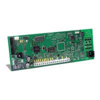
T-Link TL250/TL300
The T-Link TL250/300 modules are network internet communicators that send alarm system
information to a central station receiver. The module is pre-programmed with the most com-
monly used settings for quick installation. Default options can be custom programmed using T-
Link Console software if required.
T-Link TL300
The T-Link TL300 connects directly to the telephone output of a control panel and simulates a
telephone connection, providing a TCP/IP connection that sends predefined Contact ID codes
to the central station. The T-Link TL300 on-board zones can be used as in mode 2 (4-zone
stand-alone) and mode 3 (12-zone stand-alone). Modes 1 and 5 are not supported.
Software Version 1.0
• Supports TL250 and Modes 1, 2, 3 and 4 only.
Software Version 1.10
• Supports TL250, includes Version 1.0 options and Mode 5, TL250 DVACS panel conver-
sion (Canada only). Corresponding version numbers for SG DRL3-IP and T-Link Console
are required to ensure compatibility (i.e., SG DRL3-IP v1.10 and T-Link Console v1.10 are
required for corresponding T-Link TL250 v1.10).
NOTE: For DVACS mode an SG-DRL3-IP v1.10 receiver line card is required to communicate
with the T-Link TL250 v1.10 or higher.
• Account code extended from 6 to 10 digits.
Software Version 1.20
• Supports TL250 and TL300 and all Version 1.10 options.
• Supports new zone type ‘98’ Panel Absent.
• Supports basic programming from an LCD 5500 Keypad.
• Default Installer code has changed from CAFE to 5555 for this software version
1.1 Operating Modes
Mode 1: Bell Follower (TL250 only)
In Mode 1, the T-Link TL250 monitors the Bell Output of a control panel. The system identi-
fies the Bell Output cadence and transmits the corresponding Fire or Burglar alarm reporting
code to the central station. Refer to section 3 for details
Refer to the appropriate control panel Installation Manual.
NOTE: Do not use Mode 1 for UL or ULC listed installations.
Mode 2: 4-Zone Panel (TL250 and TL300)
In Mode 2, the system is configured for 4-zone, stand alone operation. Refer to section 4.1 for
details.
Mode 3: 12-Zone Panel (TL250 and TL300)
If the T-Link TL250 detects a PC5108 expander card on power up it will automatically configure
itself for 12-zone standalone operation with normally open loops. Refer to section 4.2 for details.
NOTE: In modes 2 & 3, the connections between the PC5108 inputs or T-Link TL250 inputs and
the alarm control unit outputs (relay contacts) shall be done in metal conduit, within 20 ft.
Stand-alone operation will still require the inputs to be programmed with the desired alarm
types.
Mode 4: Standard Mode (TL250 only)
In standard mode, the system is configured as a communicator with a compatible DSC alarm
panel: Models PC4020, PC4020CF, PC5020 or PC5020CF. Refer to section 5 for details.

 Loading...