Getting Started
20MC50M00 E5
2020-10-20
32
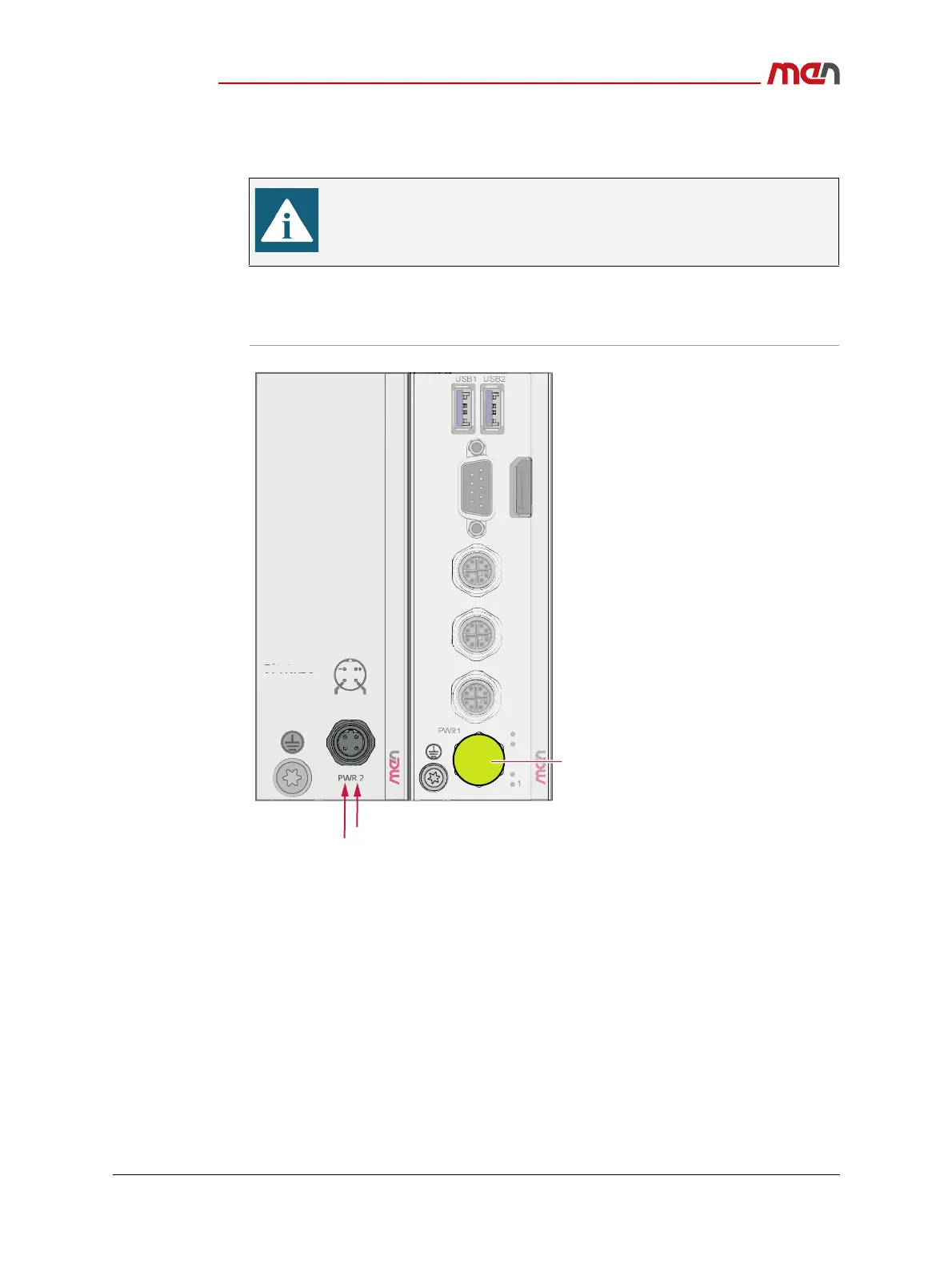
2.4.4.1 Connecting the Power Supply to an MP1/MC50M Combination
The following shows some typical configuration example of the MC50M. As the product
concept is very flexible, other configurations including ME modules are also possible.
Figure 10. Connecting the power supply to a MP1/MC50M combination
2.4.5 Starting Up the System
Carry out the following steps to start up the system:
» Power up the system.
» You can start up the UEFI firmware setup menu by hitting the <Esc> key.
» Now you can make configurations in the UEFI firmware.
The following description is only valid for product versions 06MC50Mxx.
For prototype versions 06MC50MPxx refer to Chapter Power Supply and
Table 4, Pin assignment - power supply (5-pin M12 A-coded) for
06MC50MPxx on page 46.
2
1
3
4
ETH
ETH2
24 V DC to 110 VDC
IGN2
Protecve cover
I
rr
n
:
1.
-
.
A
MP
MC50M