Hardware/Software Interface
20MC50M00 E5
2020-10-20
73
5 Hardware/Software Interface
This chapter is intended for software developers or board integrators who need deeper
knowledge of the implementation details of the MC50M interfaces and its internal
connections.
5.1 SMBus/I2C Devices
Depending on the position of the MC50M within the modular DIN-Rail system, the
SMBus address may differ. The following table gives an overview of the SMBus devices
within a complete DIN-Rail system, not only for an individual module.
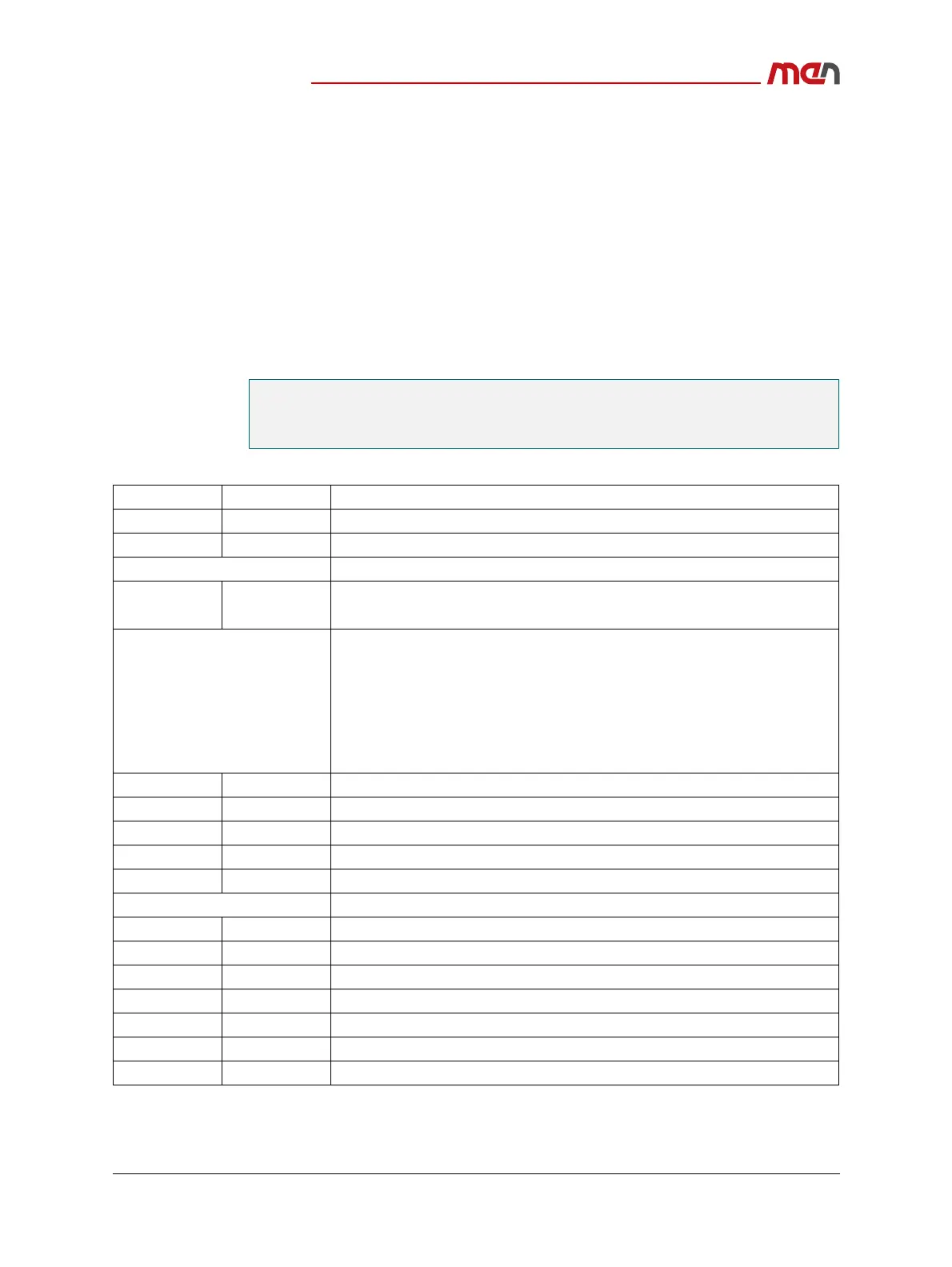
Table 34. SMBus/I2C devices
Note: All other addresses and devices are reserved for factory usage.
See Table 34, SMBus/I2C devices on page 73 and Figure 13, System positions within a
modular DIN-Rail system on page 74 to find out the relevant SMBus address for each
ME module.
8-Bit Address 7-Bit Address Function
0x64 0x32 System RTC (ERTC) on CPU module
0x9C 0x4E Board Management Controller (BMC) on CPU module
Dedicated I/O for CPU module
0x40 0x20 CPU module (position 1)
MC50M/MC50I: CPU Module User LED and Ignition Watchdog
Dedicated I/O for ME module
ME1: User LED and Wireless Card Enable Register
ME2: Not applicable
ME3: Not applicable
ME4: User LED and Wireless Card Enable Register
ME6: User LED and Wireless Card Enable Register
0x4A 0x25 ME module (position 2)
0x48 0x24 ME module (position 3)
0x46 0x23 ME module (position 4)
0x44 0x22 ME module (position 5)
0x42 0x21 ME module (position 6)
Board information EEPROM
0xAE 0x57 CPU module (position 1)
0xAC 0x56 Carrier board of CPU module (position 1)
0xAA 0x55 ME module (position 2)
0xA8 0x54 ME module (position 3)
0xA6 0x53 ME module (position 4)
0xA4 0x52 ME module (position 5)
0xA2 0x51 ME module (position 6)