Hardware/Software Interface
20MC50M00 E5
2020-10-20
74
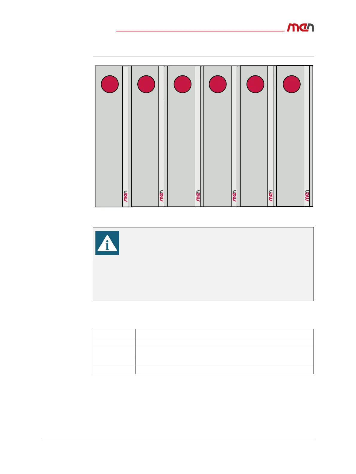
Figure 13. System positions within a modular DIN-Rail system
5.1.1 CPU Module User LED and Ignition Watchdog
Table 35. CPU module user LED and ignition watchdog register mapping
Note on 8-Bit/7-Bit Addressing
8-bit addressing is compliant to the Windows nomenclature. The last
bit, which is used as the read/write bit, is added to the address
(0 = write, 1 = read).
If you use MDIS driver software, use 8-bit addresses, with any OS.
7-bit addressing is used, e.g., under Linux. A ’0’ is added at the
beginning of the address so that all consecutive address bits are moved
one bit to the right.
If you use standard I2C commands under Linux, use 7-bit addresses.
Address Description
0x00 User LED and Ignition Watchdog Data Register (read)
0x01 User LED and Ignition Watchdog Data Register (write)
0x02 Reserved
0x03 User LED and Ignition Watchdog Configuration Register
1 2 3 4 5 6
CPU
module
including
carrier
ME module
ME module ME module ME module ME module