Do you have a question about the Dukane Infinity Series and is the answer not in the manual?
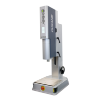
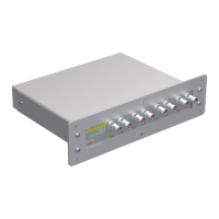
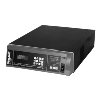
Describes the components of the Infinity Series Servo Ultrasonic Press System, including press, generator, and HMI.
Provides essential information for setting up and operating the Dukane Infinity ultrasonic servo welder.
Explains how figures and tables are identified and numbered within the manual.
Defines the meaning and usage of NOTE, CAUTION, and WARNING statements for safety.
General recommendations for safe and efficient operation of the ultrasonic press system.
Details on safe operating practices, potential hazards, and protective measures.
Information on electrical safety, including grounding requirements for the system.
Specific instructions for proper grounding of electrical power in North America.
Guidelines for proper grounding of electrical power for international use.
Explains the importance and method of grounding for effective RFI suppression.
Details on optical operate switches and compliance with OSHA regulations.
Description of the Safe Torque Off (STO) safety feature and its operating modes.
Covers FCC, CE Marking, IP Rating, UL, and CAN/CSA compliance for the equipment.
Pre-installation considerations including LOTO, power, lifting, and placement.
Explanation and procedure for using Lockout/Tagout (LOTO) devices for safety.
Details AC voltage and current needs for generators and thrusters.
Table listing AC power requirements for various Dukane Infinity generators.
Table listing AC power requirements for Dukane Infinity thruster models.
Specifies the AC power requirements for the Dukane HMI unit.
Step-by-step instructions for unpacking the ultrasonic press system components.
Guidelines and recommendations for placing the press system on a workbench.
Details on the required sturdiness and stability of the workbench for safe operation.
Methods and safety precautions for lifting and placing the press system.
Diagrams showing mounting hole locations for X4 and X3 system models.
Diagrams showing mounting hole locations for X1 system models.
Diagrams showing mounting hole locations for X2 system models.
Illustrates the appearance of an X2 system with a round column.
Illustrates the appearance of an X2 system with a rigid column.
Instructions and a table for connecting all system components correctly.
Table detailing the pinout configuration for the J5 System Input/Output connector.
Detailed descriptions of each signal and its function on the J5 connector.
Further detailed descriptions of signals and their functions on the J5 connector.
Instructions for installing and setting up tooling for the 43NTX1N model.
Steps for securely mounting the fixture onto the press base for the 43NTX1N model.
Procedure for installing the ultrasonic stack module into the press for the 43NTX1N model.
Steps for safely removing the ultrasonic stack module from the 43NTX1N model.
Instructions for separating the module block from the ultrasonic stack for the 43NTX1N.
Procedure for orienting the ultrasonic stack and horn assembly for the 43NTX1N model.
Instructions for installing and setting up tooling for the 43NTX2N model.
Steps for securely mounting the fixture onto the press base for the 43NTX2N model.
Procedure for installing the ultrasonic stack module into the press for the 43NTX2N model.
Steps for safely removing the ultrasonic stack module from the 43NTX2N model.
Procedure for orienting the ultrasonic stack and horn assembly for the 43NTX2N model.
Instructions for installing and setting up tooling for the 43NTX3N model.
Steps for securely mounting the fixture onto the press base for the 43NTX3N model.
Procedure for installing the ultrasonic stack module into the press for the 43NTX3N model.
Steps for safely removing the ultrasonic stack module from the 43NTX3N model.
Instructions for separating the module block from the ultrasonic stack for the 43NTX3N.
Procedure for orienting the ultrasonic stack and horn assembly for the 43NTX3N model.
Instructions for installing and setting up tooling for the 43NTX4N model.
Steps for securely mounting the fixture onto the press base for the 43NTX4N model.
Procedure for installing the ultrasonic stack module into the press for the 43NTX4N model.
Steps for safely removing the ultrasonic stack module from the 43NTX4N model.
Procedure for orienting the ultrasonic stack and horn assembly for the 43NTX4N model.
Procedure for adjusting the thruster's vertical position on X1, X3, and X4 models.
Procedure for adjusting the thruster's vertical position on X2 models.
Procedure for properly aligning the fixture to the horn for consistent welds.
Overview image identifying the main components of the press system.
Detailed identification of manual controls and display elements on the press.
Specific details and functions of the operating and safety switches.
Detailed explanation and operation of the Emergency Stop (Abort) switch.
Identification of connection ports on the Human Machine Interface (HMI).
Introduction to the IQ Explorer 3 software used for configuration and setup.
Highlights the main features and capabilities of the IQ Explorer 3 software.
Step-by-step guide for initial setup and connection of IQ Explorer 3.
Configuration options for initiating weld cycles within the software.
Setting trigger type, force, and maximum trigger time parameters.
Explanation of various trigger types and advanced configuration options.
Setting the horn's approach speed before reaching the trigger position.
Defining the machine travel position where the system begins to sense for trigger force.
Procedure to teach the system the correct sensing start position.
Configuration and explanation of the Melt-Detect feature for weld process control.
Description of available weld methods: Distance, Position, Energy, Peak Power, Force Change, Force Rate.
Setting the primary method for the weld process, such as Distance.
Selecting and configuring a secondary method to end the weld phase.
Configuring constant or segmented weld speed profiles for optimal welding.
Configuration of post-weld parameters for weld bond strength and repeatability.
Explanation of Dynamic Hold and Static Hold methods for post-weld processing.
Setting up process limits and their behavior for weld quality analysis.
Detailed descriptions of various process limits used for weld characteristic monitoring.
Defining acceptable upper and lower limits for part characteristics and weld quality.
Procedure for scanning the ultrasonic stack to optimize frequency for startup.
Procedure for testing the ultrasonic stack's operational parameters after scanning.
Instructions on how to initiate and run a weld cycle using the system.
How to view weld results and analyze performance graphs in the Cycle Data tab.
Table detailing specifications for various thruster models (stroke, force, speed, weight).
Recommended temperature, air particulate, and humidity guidelines for operation and storage.
Table listing model numbers with corresponding drawing numbers for layout references.
Explanation of the numbering system used for Infinity generators.
Explanation of the numbering system used for Infinity system configurations.
Common alarm codes, their explanations, and recommended solutions for the servo press system.
Additional alarm codes, explanations, and solutions for troubleshooting.
More common alarm codes, their explanations, and recommended solutions.
Further alarm codes, explanations, and solutions for troubleshooting.
Final set of alarm codes, explanations, and solutions for the servo press system.
Guidelines for maintaining sheet metal covers, ventilation slots, and AC power cords.
Detailed steps for performing semi-annual maintenance on the thruster and system.
Information required when contacting Dukane about a service-related problem.
The official mailing address for Dukane IAS.
Details about Dukane's website for product information and downloads.
Provides a link to access application support resources from Dukane.
Instructions on how to find a local Dukane representative.
Information about Dukane's ISO certification, its objectives, and requirements.
| Brand | Dukane |
|---|---|
| Model | Infinity Series |
| Category | Welding System |
| Language | English |