11
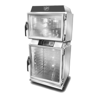
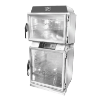
Owner's Manual for DUKE TSC Proofer Oven
with Touch Screen Controls
This equipment is intended to be connected to a
potable water supply system under pressure and is
to be installed with adequate backflow protection
to comply with all applicable federal, state, and
local codes.
Water supply pressure for proper operation shall be:
Minimum 40 PSIG(275 KPa)
Maximum 65 PSIG(448 KPa)
measured at water line inlet to the equipment.
If so equipped, regular maintenance is required to
replace the water filter cartridge at least once per
year, and to clean the inlet water screen at least
once per year. Consult state/local codes for any
additional requirements.
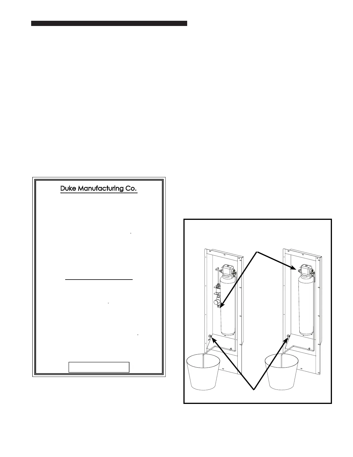
INSTALLATION OF WATER FILTER
Install new filter by removing sanitary cap from top
of cartridge, insure two black O-rings are in place,
then lift up into filter head and rotate cartridge
1/4 turn counter clockwise until it comes to a complete
stop. Flush 2 gallons (5.6 Liters) of water through the
new filter before using proofer to purge air from filter.
Remove hose from bottom of proofer by loosening
the compression nut at the disconnect fitting
and pull hose out. Place hose over container and
turn on water. It will take a minute for the filter
to fill before water flows out of hose into container.
once filter is flushed with 2 gallons (5.6 Liters) of water,
turn off water supply again, insert hose into water line
disconnect, tighten compression nut and turn
water supply on again. Check for leaks at
connection fittings.
Patent(s) Pending
INSTALLATION OF WATER FILTER
1. Install new lter by removing sanitary cap from
top of cartridge, insure two black O rings are
in place, then lift up into lter head and rotate
cartridge 1/4 turn counter clockwise until it
comes to a complete stop.
• Flush 2 gallons (5.6 Liters), of water
through the new lter before using proofer
to purge air from lter. Remove hose
from bottom of proofer by loosening the
compression nut at the disconnect tting and
pull hose out. Place hose over container and
turn on water. It will take a minute for the
lter to ll before water ows out of hose
into container.
• Once lter is ushed with 2 (5.6 Liters),
gallons of water, turn o water supply
again, insert hose into water line disconnect,
tighten compression nut and turn water
supply on again. Check for leaks at
connection ttings.
Figure 3: Water Filter (Flushing 2 gallons
(5.6 Liters), of water)
The two main components of the Duke backow
preventer system are:
• Dual Check Valve type backow preventer
that conforms to ANSI/ASSE standard #1024
and is CSA standard B64.6 certied.
• Inlet water strainer equipped with 100-mesh
screen and installed up stream of the backow
preventer. The screen is conveniently located
on the rear panel of the proofer, below the
backow preventer, for easy access during
cleaning/replacement.
Water Line
Disconnect Fitting
Factory Installed
or Kit Backow
Preventer Inlet
Water Connection
Inlet Water
Connection
Point
Water Connection
if Backow
Preventer is Not
Required
acting check valves, internally force-loaded
to a normally closed position and designed/
constructed to operate under intermittent or
continuous pressure conditions.
 Loading...