SECTION 4 - HYDRAULIC ADJUSTMENTS
18
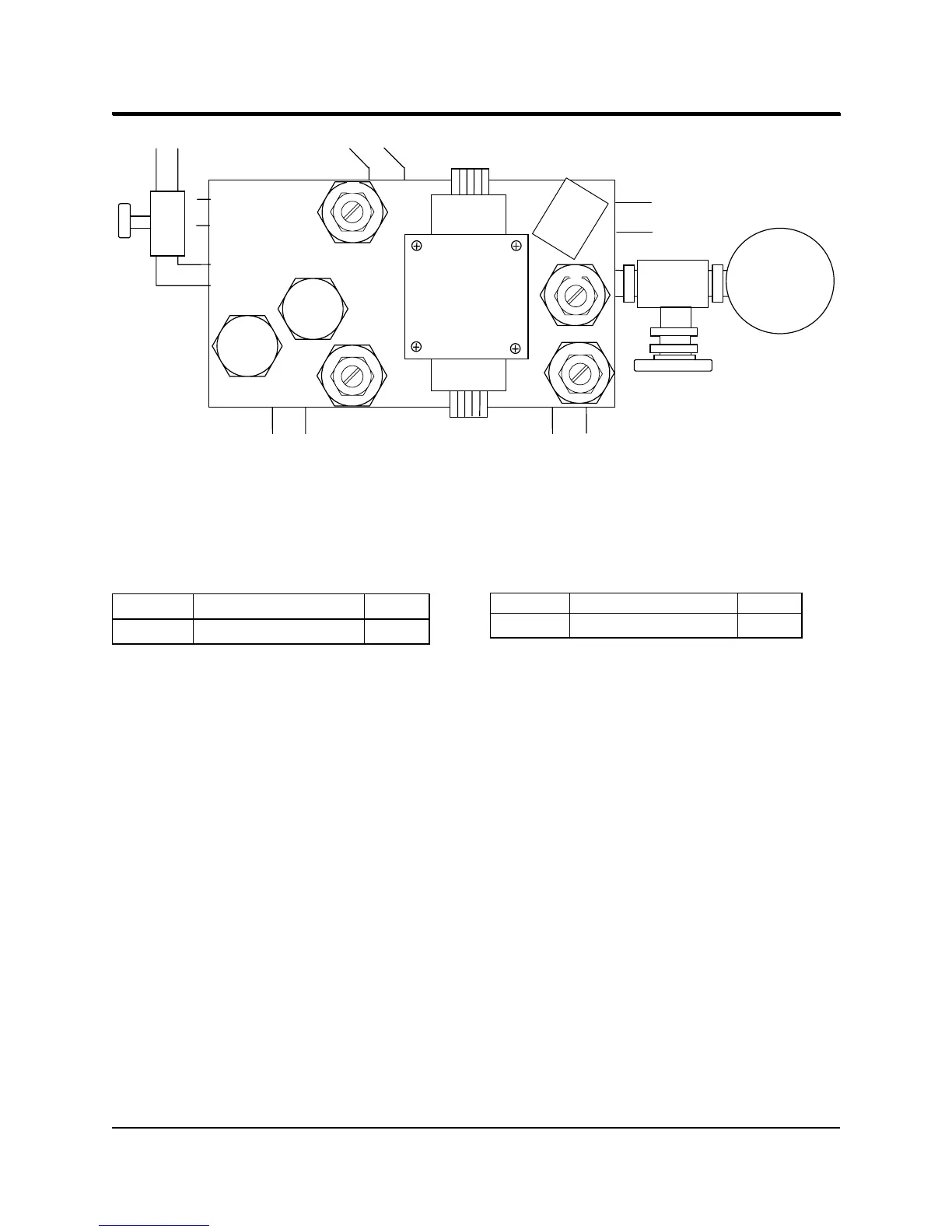
TAP 1
17
06
09
TAP 2
PRESSURE
GAUGE 2
PERFORM THE FOLLOWING ADJUSTMENTS IN THE ORDER SPECIFIED
Please Note: You will need an assistant to push the yellow cutter buttons during these adjustments.
VALVE 17 - RELIEF VALVE
ADJUST PRESSURE READING GAUGE
VALVE 17
95 +/- 5 kg/cm
2
2
PURPOSE: This adjustment sets the maximum
pressure for the hydraulic system. It prevents motor
overload.
PROCEDURE:
1. Supply hydraulic pressure to gauge 2 by opening
tap 2.
2. Shut off the supply of hydraulic pressure to the
pressure gauge on the front of the machine by
closing tap 1. Note the gauge is not shown in the
illustration above.
3. Turn on the 660 cutter.
4. Activate the knife and the clamp by having an
assistant push both yellow cutting buttons
simultaneously.
5. Loosen the lock nut on the relief valve 17.
6. While observing the reading on gauge 2, adjust
valve 17 until the pressure indicated is 95 ± 5
kg/cm
2
.
7. Tighten the lock nut on valve 17.
8. Close tap 2 and open tap 1.
VALVE 06 - RELIEF VALVE
ADJUST PRESSURE READING GAUGE
VALVE 06
30
+/-
3 kg/cm
2
2
PURPOSE: Valve 06 adjusts the low pressure for
the foot pedal and the blade change mode.
PROCEDURE:
1. Supply hydraulic pressure to gauge 2 by opening
tap 2.
2. Loosen the lock nut on the relief valve 06.
3. Have an assistant activate the clamp by pushing
the foot pedal down.
4. While observing the reading on gauge 2, adjust
valve 06 until the pressure indicated is 30 ± 3
kg/cm
2
.
5. Tighten the lock nut on the relief valve 06.
6. Close tap 2.
660P CUTTER
4 - 2
https://www.supplychimp.com