EasyManua.ls Logo

Duplo DC-616 Service Manual

Duplo DC-616
210 pages
To Next Page IconTo Next Page
Page #1 background imageLoading...
Page #1 background image
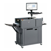
SLITTER / CUTTER / CREASER
DC-616
Apr. 2014 Revision 0
DUPLO DC-616 S2-Y1540

Table of Contents

Other manuals for Duplo DC-616

Questions and Answers:

Duplo DC-616 Specifications

General IconGeneral
BrandDuplo
ModelDC-616
CategoryPaper Cutters
LanguageEnglish

Summary

Introduction

How to Use This Service Manual

Explains the structure and conventions of the service manual.

Safety Instructions

Provides crucial safety warnings and precautions for operating and servicing the machine.

Trademarks

Lists registered and unregistered trademarks of companies and products mentioned in the manual.

Please Note

Informs about potential changes to specifications and encourages clarification for any misunderstandings.

How to Use This Service Manual

Safety Instructions

Highlights safety markings and instructions of particular importance for preventing injury.

For Maintenance Operation

Introduces instructions for correct operation and useful information for maintenance.

Safety Instructions

Cautions Regarding Installation Location

Details environmental and placement cautions to ensure safe and proper machine operation.

Cautions for Installation Work

Outlines essential precautions related to power supply, grounding, and extension cords during installation.

Cautions for Maintenance, Inspection and Servicing

Provides warnings and recommendations for safe practices during maintenance and servicing procedures.

Warning Labels

Label Identification and Placement

Identifies various warning labels on the machine and their corresponding part numbers for replacement.

Chapter 1 Introduction

Specifications

Lists the technical specifications of the DC-616 machine, including dimensions and capabilities.

Part Names and Functions

Details the names and functions of various components, including external appearance, internal parts, control panel, and LCD.

Machine Dimensions

Provides the physical dimensions of the DC-616 machine in millimeters.

Chapter 2 Operation in General

Paper Feed Section Operation

Covers the description, operation, and detailed part operations of the paper feed section.

Double Feed Detection Section Operation

Explains the description, operation, and part operations of the optional double feed detection section.

CCD Section Operation

Details the description, operation, and part operations of the CCD section for barcode and REG mark reading.

Margin Slitter Section Operation

Covers the description, operation, slitter blade, and part operations for the margin slitter section.

Center Slitter Section Operation

Explains the description, operation, slitter blade, and part operations for the center slitter section.

Cutter Section Operation

Details the description, operation, and part operations for the cutter section.

Creaser Section Operation

Covers the description, operation, and part operations for the creaser section.

Main Drive Section Operation

Provides the description for the main drive section.

Exit Tray Operation

Details the description of the exit tray and its settings.

Exterior Operation and Safety Switches

Covers the description, operation, and part operations related to the machine's exterior covers and interlock switches.

Barcode Functionality

Explains how barcodes enable automatic job setup and lists the specifications for barcode type and resolution.

REG Mark Functionality

Details the description, specifications, and position of the REG mark for image drift compensation.

Chapter 3 Mechanism

Exterior Component Removal

Lists various external covers and interlock switches that can be removed for access or maintenance.

Paper Feed Section Disassembly

Provides step-by-step instructions for removing components of the paper feed section, including plates and units.

Double Feed Detection Unit Removal

Details the process for removing the ultrasonic sensor unit and its associated components.

CCD Section Component Removal

Explains how to remove the CCD unit and related sensors like PPS2.

Margin Slitter Section Disassembly

Guides the user through the removal of the margin slitter module, blades, and position motor.

Center Slitter Section Component Removal

Provides instructions for removing the center slitter module, blades, and position motor.

Cutter Section Component Removal

Details the steps for removing the cutter module and slitter blade module.

Creaser Section Component Removal

Covers the removal of creaser motor, belt, sensors, and blades for the creaser section.

Main Drive Section Component Removal

Guides the user through the removal of the main motor, drive belt, rollers, and perforation tool.

Electrical System Component Removal

Provides instructions for removing PCB units, power supply, and control panel components.

Chapter 4 Adjustment

Exterior Component Adjustments

Details adjustments for top cover, front cover, and exit interlock switches on the machine's exterior.

Paper Feed Section Adjustments

Covers adjustments for shutter solenoid, elevator limit switches, and paper feed unit settings.

CCD Section Adjustments

Explains the adjustment procedures for the CCD and PPS2 sensors.

Margin Slitter Section Adjustments

Details adjustments for margin slitter home position sensor, jam sensor, and slitter position motor/belt.

Center Slitter Section Adjustments

Covers adjustments for center slitter home position sensor and slitter position motor/belt.

Cutter Section Adjustments

Outlines adjustments for cutter motor and cutter home position sensor.

Creaser Section Adjustments

Details adjustments for creaser motor/belt, encoder sensor, and home position sensors.

Main Drive Section Adjustments

Covers the adjustment procedure for the main motor drive belt.

Chapter 5 Maintenance Checks

Maintenance Cycle and Cleaning Procedures

Discusses guaranteeing the maintenance cycle and provides instructions for cleaning and oiling machine parts.

Periodic Maintenance Checklist

Presents a checklist for 6-month periodic maintenance tasks for sensors, belts, cutter, gears, and sliders.

Recommended Parts List

Lists recommended replacement parts with part numbers, MTBF, and remarks for coated paper usage.

Chapter 6 Troubleshooting

Common Error Message Troubleshooting

Lists common error messages and their corresponding troubleshooting steps, referencing page numbers for solutions.

Error Detection Conditions Explained

Explains the specific conditions that trigger various error codes, such as paper jams, sensor issues, and communication errors.

Paper Jam Causes and Prevention Strategies

Identifies major causes of paper jams and provides preventive actions, including recommended paper types to avoid.

Slitter Blade Intersection Correction Procedure

Describes the procedure to correct intersecting slitter blades, particularly in cases of heavy document jams.

Chapter 7 HELP Mode

HELP Mode List and Access Procedures

Provides a comprehensive list of available HELP modes, their functions, categories, and page numbers for access.

HELP Mode Finishing and Settings

Explains how to finish a HELP mode session and how to set other specific HELP mode numbers.

Accessing Service Person JOBs

Details the procedure for accessing specific JOBs designated for service personnel.

Specific HELP Mode Descriptions

Provides detailed explanations of various HELP modes, including functions and operating procedures.

Chapter 8 Others

Electronic Parts Identification and Function

Identifies the position and function of various electronic parts, including switches, sensors, motors, and PCBs.

Service Person JOBs Reference

Lists and describes various Service Person JOBs used for machine setup, testing, and calibration.

Overall Wiring Layout Diagrams

Provides detailed wiring layout diagrams for the machine's electrical system, showing connections between components.

Chapter 9 PC Controller

PC Controller Main Menu Overview

Introduces the main menu of the PC Controller software, outlining its functions and interface elements.

Maintenance Menu Operations

Details operations within the Maintenance Menu, including managing maintenance data, option modules, and language settings.

Data Folder Contents and Management

Lists the files and folders contained within the DC-616 PC Controller data folder.

Maintenance Data Procedures

Covers procedures for confirming saved maintenance data, uploading data, setting up machine connection, and language management.

Software and Driver Version Confirmation

Explains how to confirm the versions of the PC Controller software and its associated drivers on different operating systems.

Related product manuals