28
Chapter 2 4 Margin Slitter Section
S2-Y1540
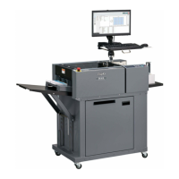
1. Description
The margin slitter is provided (slitter 1, 2) on both
sides to cut the paper along the traveling direction
by means of the rotary blades. The cut-off margin is
dropped into the waste box.
2. Operation
The lead screw is turned by means of the stepping
motor to cause the margin slitter to move from the
home position by the specifi ed amount of pulse.
3. Slitter Blade
The slitter blades are constructed so that the lower
blade of the slitter is tilted relative to the paper feed
direction. This makes the upper and lower slitter
blades contact at only one point to maintain the clean
cut even after the slitter blade has worn out.
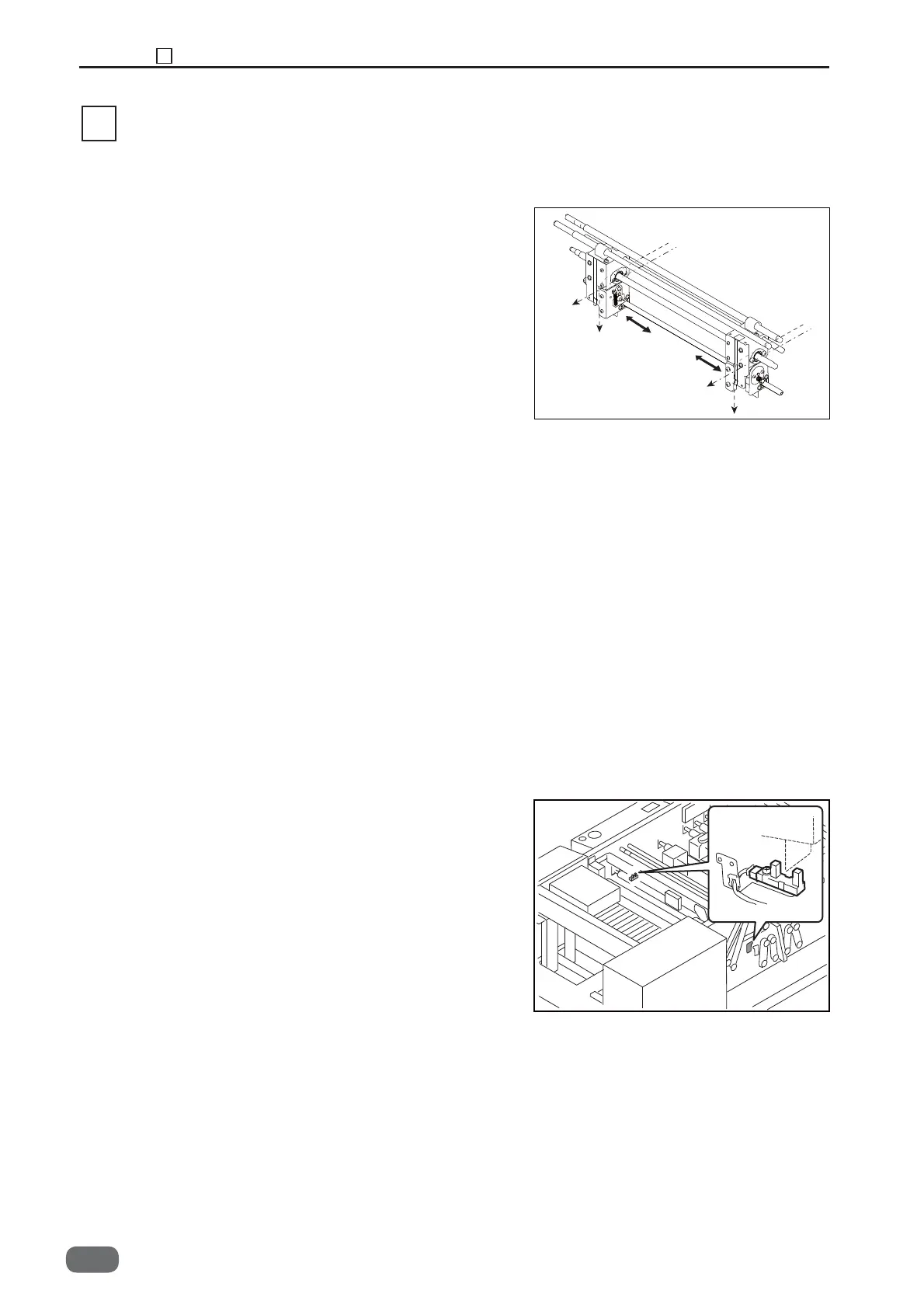
4. Operation of Each Part
1. Margin Slitter Home Position Sensor
<Operation>
Margin slitter HP sensor detects the home position
of the margin slitter by the photo-micro sensor, and
controls the margin slitter position based on the
amount of pulse from the home position.
-0
4 Margin Slitter Section