97
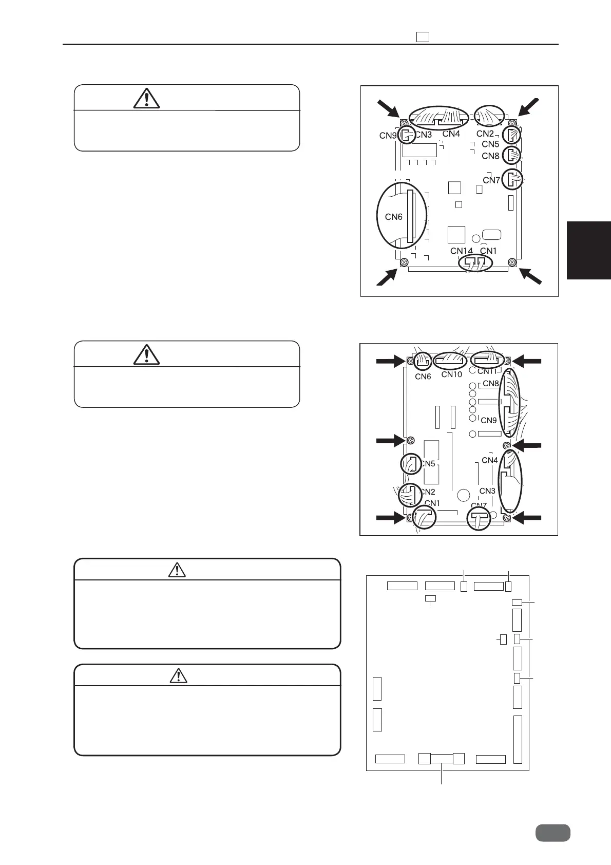
Chapter 3 10 Electrical System Section
3
S2-Y1540
1. Remove the cover.
2. Disconnect 11 connectors.
3. Take out the six screws, and remove the drive PCB
unit.
* Pay attention to the terminals at the time of
installation to prevent them from touching with each
other.
1. Remove the cover.
2. Disconnect 10 connectors.
3. Take out the four screws, and remove the PCB unit.
* Pay attention to the terminals at the time of
installation to prevent them from touching with each
other.
(3) Removing the Main PCB Unit
(4) Removing the Drive PCB Unit
CN 1
CN 2
CN 8
CN 3
CN 7
CN 5
CN 6 CN 10
CN 11
CN 9
CN 4
F6
F206
F205
F207
F202
F201
F204
F203
F6:250V 10A
TLC10AN4
● Always remove the power cord plug from
the outlet before replacing a PCB Unit.
WARNING
● Always remove the power cord plug from
the outlet before replacing a PCB unit.
WARNING
Fuse: F6
● For continued protection against fi re hazard,
replace only with the same type and rating fuse.
CAUTION
Fuse: F201 - F207
● When the fuse of the drive PCB unit was
damaged, replace the drive PCB unit.
(See→P.54)
(See→P.54)
CAUTION
Connector
Connector
Connector
Screw
Screw
Screw
Screw
Screw
Screw
Screw
Screw
Screw
Screw
-0