83
Chapter 3 7 Cutter Section
3
S2-Y1540
7 Cutter Section
1. Open the top cover.
2. Remove the covers F, R.
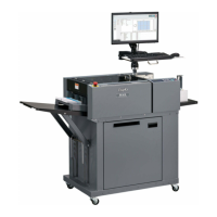
3. Disconnect the motor connector.
4. Take out one screw, and draw out the home
position sensor bracket.
(1) Removing the Cutter Module
5. Take out the fi ve screws, and draw out the cutter
module.
* Adjustment required at the time of installation
(See→P.105)
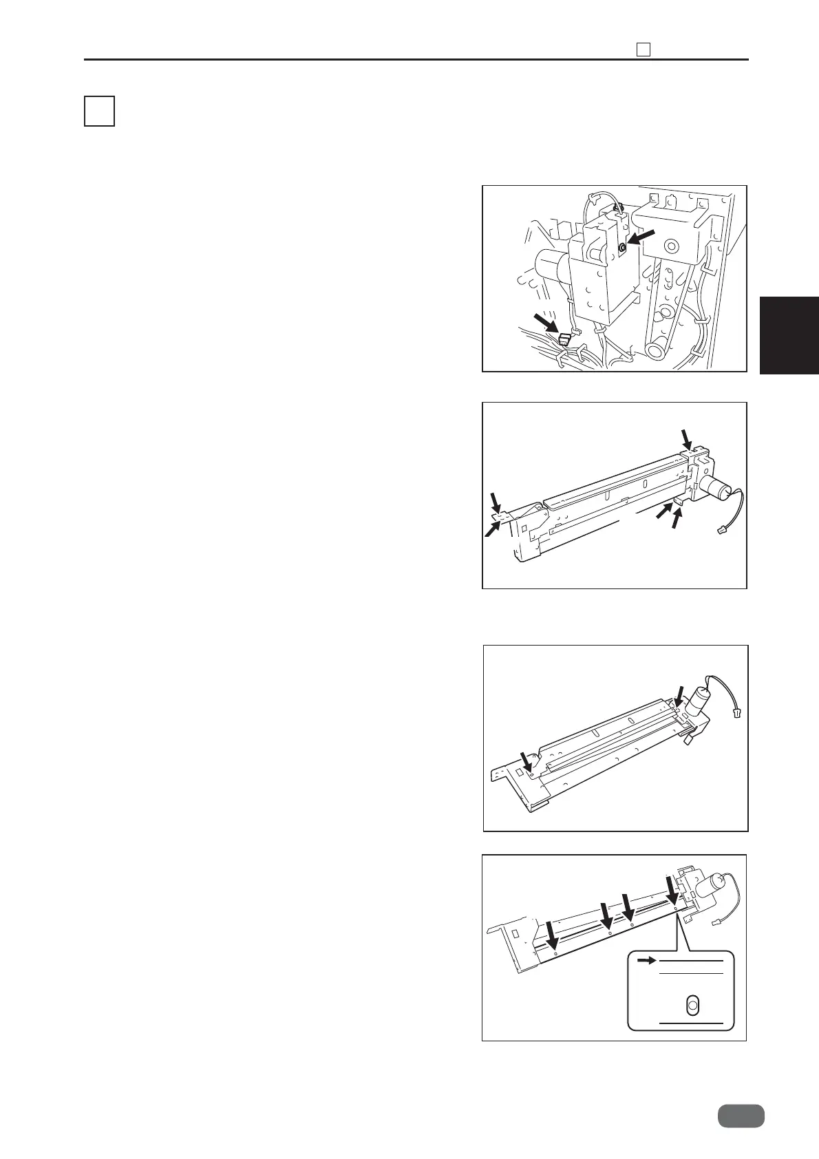
● Removing the Slitter Blade Module
1. Take out the two screws, and remove the lock plate
unit.
2. Take out the four screws, and remove the under
guide.
* Align the top of the under guide with the top of the
blade at the time of installation.
3. Take out the three screws, and remove the bracket.
(See→P.52) (See→P.53)
(See→P.87)
Connector
Screw
Screw
Screw
Screw
Screw
Screw
Screw
Screw
Screw
Screw
Screw
Screw
-0