36
Chapter 2 7 Creaser Section
S2-Y1540
3. Operation of Each Part
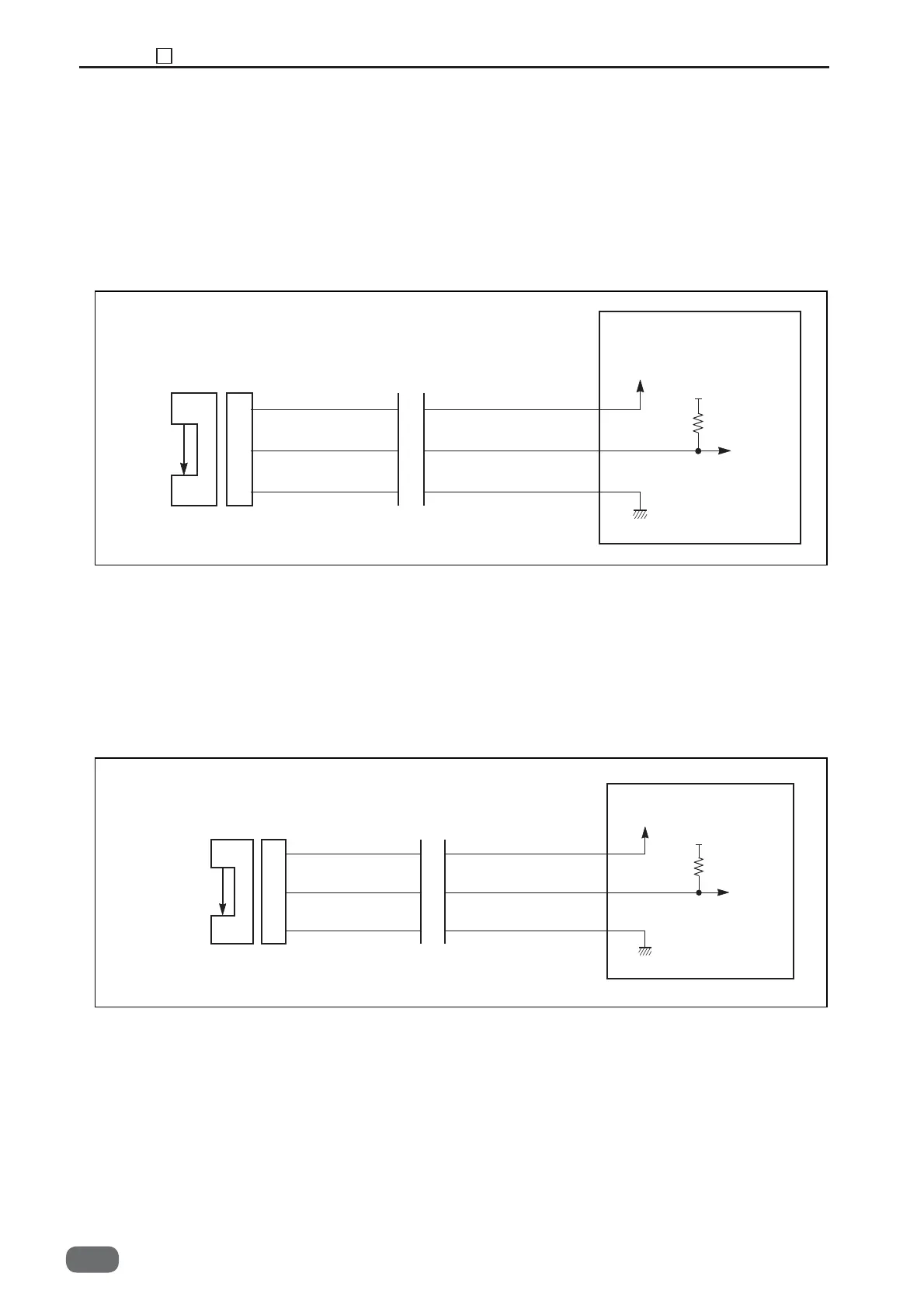
1. Crease Lower Blade Home Position Sensor
<Operation>
This sensor detects the crease home position by
sensing the sensor plate attached to the eccentric
shaft by means of the photo-micro sensor.
<Circuit diagram>
5V
5V
1
2
3
4
5
6
CN3-13
14
15
CREASE LOW HP sensor
Red
Light green
Main PCB unit
Blue
2. Crease Home Position Sensor
<Operation>
This sensor detects the crease home position by
sensing the sensor plate attached to the eccentric
shaft by means of the photo-micro sensor.
<Circuit diagram>
5V
5V
1
2
3
1
2
3
CN3-10
11
12
CREASE HP sensor
Red
White
Blue
Main PCB unit
Light not transmitted: 5V
Light transmitted: 0V
Light not transmitted: 5V
Light transmitted: 0V
-0