37
Chapter 2 7 Creaser Section
2
S2-Y1540
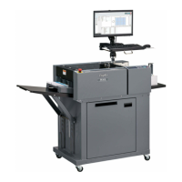
<Circuit diagram>
3. Creaser Lower Blade Encoder Sensor
<Operation>
Creaser lower blade encoder sensor adjusts the crease
depth in three levels from the lower limit position by
reading out the encoder attached to the crease depth
adjustment motor by means of the photo-micro sensor.
5V
5V
1
2
3
7
8
9
CN3-16
17
18
CREASE ENCODER
Red
Purple
Main PCB unit
Blue
4. PPS4
<Operation>
The
light from the PPS photo-emitting PCB is
received by the PPS photo-detecting PCB. The
presence or non-presence of the paper is determined
by the
receiving amount.
PPS4 detects the passing paper and paper jam in the
cutter and crease areas.
<Circuit diagram>
5V
1
2
3
5V
5V
15
CN4-13
14
1
3
1
2
11
12
1
2
3
PPS4
Red
Main PCB unit
Gray
Blue
Red
Orange
Light not transmitted: 5V
Light transmitted: 0V
Light not transmitted: 5V
Light transmitted: 0V
-0