Connection of the microphone terminals is performed through a RJ 45 plug (8-pole) which is plugged into
the PAGING STATION [57] socket. All utilized microphone terminals have to be connected parallel. Power
supply, LF-signal, and data signals are provided through this connection. Prior to operating the system
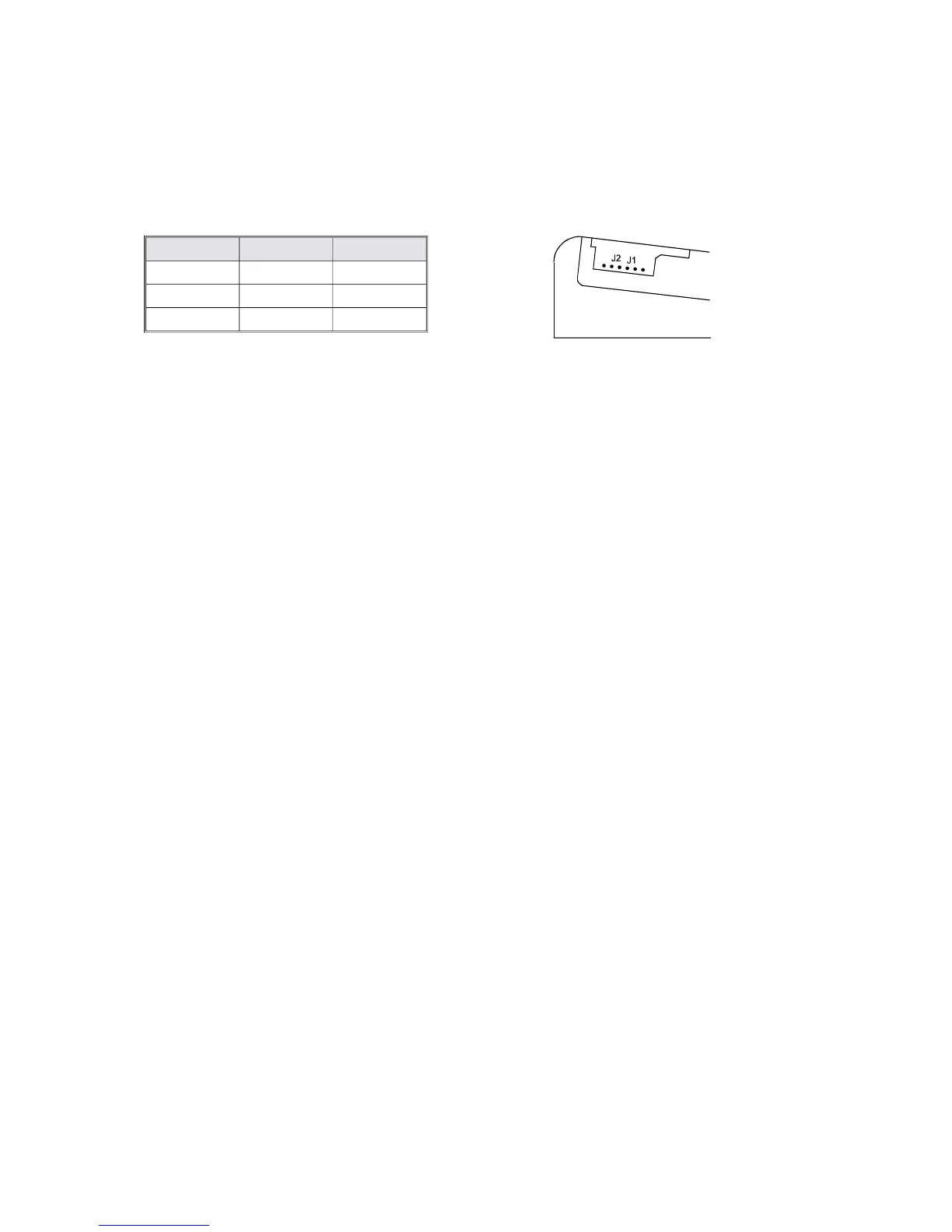
with the microphone terminals, you have to assign a unique ID (address) to each MT 2005 that is going
to be connected. Thus, you have to detach the left side panel and match the jumpers J1 and J2 according
to your requirements. (ID address 1 is factory presetted; other possibilities are addresses 2 and 3) (refer
to the following table).
address jumper1 jumper2
1 inserted open
2 open inserted
3 open open
Pin assignment of the RJ 45-connector, for the connection of up to three MT2005 or one PTT microphone
The microphone terminal connector’s (PAGING STATION, 57) pin assignment is as follows; cabling has
to be performed using a common 8-pole shielded cable connecting all microphone terminals incorporated:
1 operation voltage +24 V
2 operation voltage ground potential, reference potential
3 signal wire “paging station detected”
(connected to the paging station’s internal grounding)
4 data wire RS 485, conductor A
5 data wire RS 485, conductor B
6 PTT (contact to ground potential, only when using a PTT microphone)
7 NF-wire, el. Balanced
8 NF-wire, el. balanced
please note the cable-pairs: 1+2, 3+6, 4+5, 7+8!
Cable length
The minimum allowable voltage on the microphone terminal is 15.5 volts. The maximum power consump-
tion of each MT2005 at this voltage is 123 mA. At cut-off the battery is supposed to deliver 21.6 volts,
internal voltage drops reduce the output voltage for the microphone terminals to 18.1 volts. Thus, the
maximum allowable voltage drop on the microphone terminal cabling is not to exceed 2.6 volts.
The maximum permissible cable lengths between the CPA 2000 and the paging station(s) are as follows
(cabling can be carried out in stellar-connection or as a bus-system, where – because of the RS 485
interface definitions – the total length of the cable network is not to exceed 1000 meters):
using cable 4 x 2 x 0.6 l(Y)STY using cable 4 x 2 x 0.8 l(Y)STY
one microphone terminal 160 m 280 m
two microphone terminals 80 m 140 m
three microphone terminals 50 m 90 m
The MIC / LINE [45] switch of the CPA 2000’s input 2 has to be engaged, adjusting it for low sensitivity
and the corresponding GAIN [46] control approximately has to be set to its center position. Further, no
sound source can be connected to the INPUT 2 [44]. Set the priority function according to paragraph 7.
The signal’s loudness is controlled by the MIC 2 [2] control while the sound gets adjusted using the
TREBLE [9] and BASS [10] controls.
33


 To Next Page