DSP 260
24 Owner‘s Manual
off frequency will be attenuated. (See response curve.)
Use the < Select > buttons to navigate to the filter setting you wish to adjust, and the Value Up and Down
buttons to alter these settings. Press the Value Up and Down buttons once to increment values by one
unit, or press and hold to scroll rapidly through available values. (Values do not wrap-around.)
Hi-pass
The Hi-Pass filter determines the ultimate low frequency that your sound reinforcement
system is allowed to reproduce; given the capabilities of amplifiers, speakers and
transducers. Keep in mind that the DSP 260 signal path already includes a hi-pass filter prior to the Input
PEQ DSP block. Settings to this filter in most configurations may be redundant or interactive with the initial
Hi-Pass filter.
Available parameters are Frequency and Slope. The frequency parameter determines the frequency
below which frequencies will be attenuated. The slope determines how quickly frequencies below that will
be attenuated. (See response curve.)
Use the < Select > buttons to navigate to the filter setting you wish to adjust, and the Value Up and Down
buttons to alter these settings. Press the Value Up and Down buttons once to increment values by one
unit, or press and hold to scroll rapidly through available values. (Values do not wrap-around.)
Input Channel GEQ (Graphic Equalizer) (available soon)
Use the < Select > buttons to make the top line of the Edit screen active and the Value Up and Down
buttons to navigate to the Input GEQ screen.
The DSP 260’s input signal path includes a stereo 31-band graphic equalizer after the stereo 9-band PEQ
in the signal path. This DSP block can be used for very precisely identifying, isolating and correcting
problematic frequency ranges.
Keep in mind that changes to the Input GEQ will be interactive with adjustments made in the Input PEQ.
Unexpected results can occur.
Press the < Select > buttons to move the cursor down into the GEQ frequency adjustment field.
Subsequent presses of the < Select > buttons will move the cursor forward or backwards through the
frequency adjustment field; from band to band. The selected frequency’s “fader” is highlighted in the
display. As each band is selected, its center frequency and current cut/boost setting is displayed on the top
line of the LCD display.
To adjust the amount of boost or cut for a selected frequency band, select the band with the < Select >
buttons and press the Value Up or Down buttons as required. The LCD display will reflect your changes by
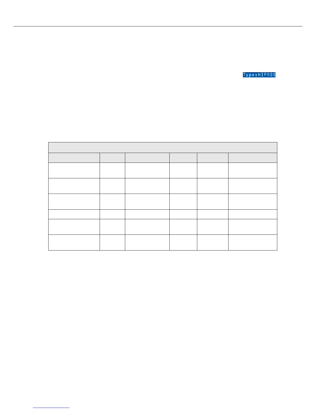
Input A/B Parametric EQ
Band Type Frequency Slope Resp / Q Gain
HIPASS HIPASS 20 Hz...20000 Hz
6dB/oct.
12dB/oct. 0.40 to 2.00
PARA EQ BAND 1-9 LOSLV 20 Hz...20000 Hz
6dB/oct.
12dB/oct.
-15.0dB to +15.0dB
HISLV 20 Hz...20000 Hz
6dB/oct.
12dB/oct.
-15.0dB to +15.0dB
PEQ 20 Hz...20000 Hz 0.40 to 20 -15.0dB to +15.0dB
LOPASS 20 Hz...20000 Hz
6dB/oct.
12dB/oct. 0.40 to 2.00
HIPASS 20 Hz...20000 Hz
6dB/oct.
12dB/oct. 0.40 to 2.00