10 CA 602 O602EN1
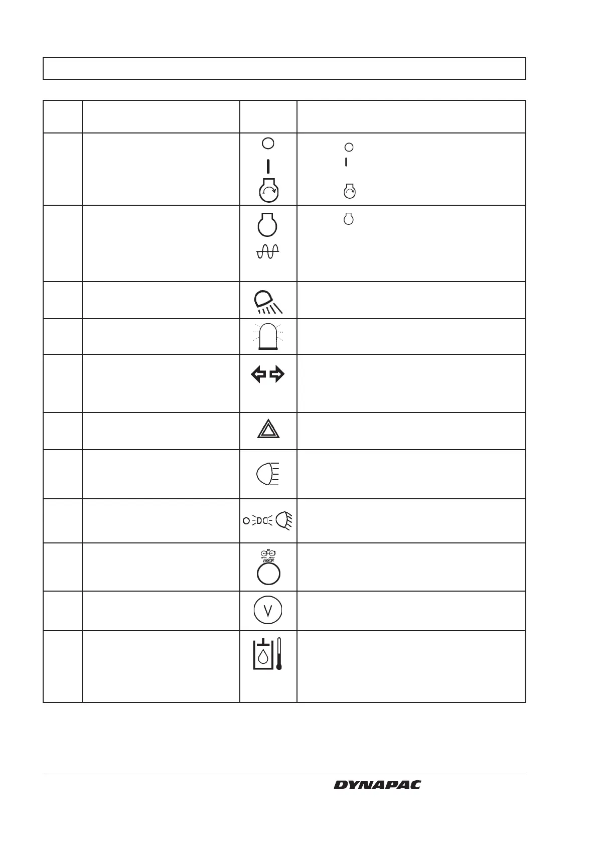
INSTRUMENTS AND CONTROLS, FUNCTIONAL DESCRIPTION
Item in Designation Symbol Function
fig. 7
1 Starter switch In mode
the electric circuit is broken.
In mode
all instruments and electric controls
are powered.
In mode
the starter motor is energized.
2 Engine revs/Frequency In mode
the engine revs are shown on
selector (Optional) instrument 13.
In the right mode the vibration frequency is
shown on instrument 13.
(The left mode has no function.)
3 Working lights rear, switch Turn to the right to switch on the working
(Optional) lights.
4 Hazard beacon, switch Turn to the right to switch on the hazard
(Optional) beacon.
5 Direction indicator, switch Turn to the left to make the left direction
(Optional) indicator flash, etc.
The flashing function is switched off in the
middle mode.
6 Hazard flashers, switch Turn to the right to switch on the hazard
(Optional) flashers.
7 Main/Dipped beam, switch Turn to the right to switch on the main beam
with control lamp (Optional) and to illuminate the switch.
Turn to the left to switch on the dipped beam.
8 Driving lighting, switch When turned right, the first setting switches
(Optional) on the parking light, the second setting
activates low beam.
9 Warning lamp, malfunctioning The hydraulic propulsion system is not
anti-spin function working satisfactorily if the lamp flashes.
(Optional) Locate and remedy the fault.
10 Voltmeter, (Optional) Indicates voltage of the electrical system.
Normally 12–15 volt.
11 Temperature gauge, Indicates temperature of hydraulic fluid.
hydraulic fluid, (Optional) Normal temperature range 65°C to 80°C
(149°F to 176°F). Stop the engine if the
meter reading exceeds 85°C (185°F).
Locate and remedy the fault.