16 CA 602 O602EN1
BEFORE STARTING
Battery disconnecter
– Switching ON
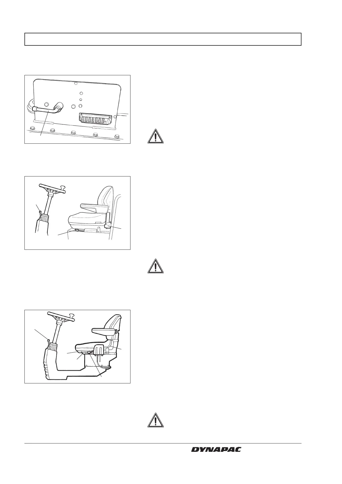
Fig. 9 Engine compartment
1. Battery disconnecter
2
Operator’s seat – Setting
1
4
3
5
Fig. 11 Operator’s station
1. Locking lever - rotation (Optional)
2. Locking lever - slope of steering
wheel
3. Locking lever - length adjustment
4. Lever - seat back slope
5. Lever - weight adjustment
1
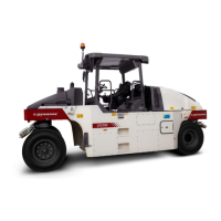
Fig. 10 Operator’s seat
1. Locking lever - length adjustment
2. Lever - weight adjustment
3. Locking lever - slope of steering
wheel
Control unit (Optional) – Setting
2
1
3
The engine hood must be unlocked during
operation, so that battery power can be
disconnected quickly if necessary.
Remember to carry out daily service. See maintenance
manual.
The battery disconnecter is located in the engine
compartment. Open the engine cover and set the key
(1) to the ON position. The entire roller will be powered.
WARNING
Adjust the operator’s seat to ensure a comfortable
posture and so that all controls are within easy reach.
The seat can be adjusted as follows:
Length adjustment (1)
Cushioning to suit weight of operator (2)
Release the locking lever (3) to adjust the steering
column to the desired slope and then lock the steering
column in its new position.
Always make sure that the seat is secure
before beginning operation.
WARNING
Always make sure that the seat is secure
before beginning operation.
The control unit has two modes of adjustment, ie,
rotation and slope of steering wheel.
Pull the lever (1) upwards to allow rotation.
Release the locking lever (2) to adjust the steering
column to the desired slope and then lock the steering
column in its new position.
The seat can be adjusted as follows:
• Length adjustment (3).
• Seat back slope (4).
• Cushioning to suit weight of operator (5).
WARNING